Volkswagen Tiguan Service and Repair Manual: Wheel Alignment
General Information and Special Tools
Special tools and workshop equipment required
- Wheel Alignment Computer -VAG1813- or VW/Audi approved wheel alignment devices
- Brake Pedal Actuator -VAG1869/2-.
- Insert Tool - 18mm -T10179-
- Shock Absorber Set -T10001-
Wheel alignment must only performed using VW/Audi-approved wheel alignment equipment!
Wheel alignment checks must always include both the front and rear axles.
Otherwise centering of toothed shaft cannot be guaranteed!
- Perform alignment using the alignment computer.
All information needed for the alignment can be found in the alignment computer.
Current data "updates" are stored in VWServiceNet.
VWServiceNet; systems; software wheel alignment computer; BeissbarthVWServiceNet; systems; software wheel alignment computer; Hunter
VWServiceNet; systems; software wheel alignment computer; CorghiVWServiceNet; systems; software wheel alignment computer; John Bean
Note
- Wheels should not be aligned until the vehicle has been driven 1,000 to 2,000 km (621 to 1242 miles), since it takes this long for the coil springs to settle.
- The individual specifications should be followed as exactly as possible when making adjustments.
When Vehicle Alignment is Necessary
- Vehicle shows handling problems.
- There is an accident damage and components were replaced.
- Axle components have been removed or replaced.
- Tire wear patterns are uneven.
Components Replaced
| Front Axle Component Replaced | Wheel Alignment Check Required | Rear Axle Component Replaced | Wheel Alignment Check Required | ||
| Yes | No | Yes | No | ||
| Lower control arm | X | Lower transverse link | X | ||
| Bonded rubber bushings for control arm | X 1) | Upper Transverse Link | X | ||
| Wheel bearing housing | X | Tie rod | X | ||
| Tie rod/tie rod end | X | Wheel bearing housing | X | ||
| Steering gear | X | Subframe | X | ||
| Subframe | X 1) | Coil spring | X | ||
| Suspension strut | X | Shock absorber | X | ||
| Stabilizer bar | X 1) | Stabilizer bar | X | ||
| Trailing Arm | X | ||||
1) Prerequisite: the subframe was secured prior to removal.
Components Removed and Installed
| Components Of Front Axle Removed And Installed | Wheel Alignment Check Required | Components Of Rear Axle Removed And Installed | Wheel Alignment Check Required | ||
| Yes | No | Yes | No | ||
| Lower control arm | X 1) | Lower transverse link | X | ||
| Wheel bearing housing | X | Upper transverse link | X | ||
| Tie rod/tie rod end | X | Tie rod | X | ||
| Steering gear | X | Wheel bearing housing | X | ||
| Subframe | X 1) | Subframe | X | ||
| Suspension strut | X | Coil spring | X | ||
| Stabilizer bar | X 1) | Shock absorber | X | ||
| Stabilizer bar | X | ||||
| Trailing arm | X | ||||
1) Prerequisite: the subframe was secured prior to removal.
Test Prerequisites
- Suspension, wheel bearing, steering and steering linkage checked for excessive play and damage.
- Tread depth difference may be no more than 2 mm on an axle.
- Tires inflated to the inflation pressure.
- Curb weight of vehicle.
- Fuel tank must be full.
- Spare tire and vehicle tools are installed in appropriate position in vehicle.
- The water container for the windshield/headlamp cleaning system must be full.
- Make sure the sliding plates and turntables are not touching the end stop when taking measurements.
Caution
Test equipment must be properly attached and adjusted; observe equipment manufacturer instructions!If necessary, contact the manufacturer for instruction on the proper use of the alignment tester.
After a certain period, wheel alignment platforms and computer equipment can lose their original leveling setting and adjustments.Wheel alignment platforms and wheel alignment analyzer/computer should be serviced and calibrated at least once a year.
- Treat these highly sensitive units carefully and conscientiously!
Measure Preparations
Special tools and workshop equipment required
- Brake Pedal Actuator -VAG1869/2-.
The lateral run-out of the wheel must be compensated for. Otherwise, measurement will result in false readings.
A correct toe-in adjustment will not be possible without performing lateral run-out compensation!
For this, observe notes by manufacturer of wheel alignment equipment.
- Perform wheel run-out compensation.
- Install the Brake Pedal Actuator -VAG1869/2-.
- Actuate the brake pedal using brake pedal actuator.
Wheel Alignment Specified Values
Specifications valid for all engine versions
- Explanation of PR. numbers can be found here.
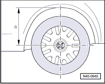
Standing heights listed in the table refer to dimension -a-.
| Front Axle | Basic suspension | Sport suspension | Basic suspension with adaptive chassis DCC | Basic suspension USA and Canada | Blue Motion |
| PR Numbers | G02/G10 | G03 | G40 | G34/G74 | G06/G07 |
| Total toe (wheels not pressed) | 10′ +- 10′ | 10′ +- 10′ | 10′ +- 10′ | 10′ +- 10′ | 10′ +- 10′ |
| Camber (in straight-ahead position) | -27′ +- 30′ | -27′ +- 30′ | -27′ +- 30′ | -27′ +- 30′ | -47′ +- 30′ |
| Maximum permissible difference between both sides | maximum 30' | maximum 30' | maximum 30' | maximum 30' | maximum 30' |
| Toe-out angle 1) with steering wheel turned 20º to left and right | 1º36′ +- 20′ | 1º36′ +- 20′ | 1º36′ +- 20′ | 1º36′ +- 20′ | 1º32′ +- 20′ |
| Caster | 7º 34′ +- 30′ | 7º 34′ +- 30′ | 7º 34′ +- 30′ | 7º 34′ +- 30′ | 7º 45′ +- 30′ |
| Maximum permissible difference between both sides | maximum 30' | maximum 30' | maximum 30' | maximum 30' | maximum 30' |
| Standing height | 430 +- 10 mm | 430 +- 10 mm | 430 +- 10 mm | 430 +- 10 mm | 410 +- 10 mm |
1) The toe angle difference can also be indicated negatively in alignment computer, depending on manufacturer.
Specified values valid for all engine versions.
- Explanation of PR. numbers can be found here → Chapter "Vehicle Data Label"
| AWD rear axle | Basic suspension | Sport suspension | Basic suspension with adaptive chassis DCC | Basic suspension US version | Blue Motion |
| Camber | -1º 20′ +- 30′ | -1º 20′ +- 30′ | -1º 20′ +- 30′ | -1º 20′ +- 30′ | -1º 20′ +- 30′ |
| Maximum permissible difference between both sides | maximum 30' | maximum 30' | maximum 30' | maximum 30' | maximum 30' |
| Total toe (at prescribed camber) | +10′ +- 10′ | +10′ +- 10′ | +10′ +- 10′ | +10′ +- 10′ | +10′ +- 10′ |
| Maximum permissible deviation from direction of rotation | maximum 20′ | maximum 20′ | maximum 20′ | maximum 20′ | maximum 20′ |
| Standing height | 440 +- 10 mm | 440 +- 10 mm | 440 +- 10 mm | 440 +- 10 mm | 430 +- 10 mm |
Overview - Wheel Alignment Procedure
Observe the Following Work Sequence!
- Pay attention to notes on wheel alignment device
Measuring Procedure
| Start | → | Perform wheel run-out compensation. | → | Bounce vehicle | ||||
| ↓ | ||||||||
| Turn the steering wheel into the straight ahead position and secure it 1) | ← | Measure vehicle height | ← | Install the Brake Pedal Actuator -VAG1869/2-. | ||||
| ↓ | ||||||||
| Check camber at front axle | → | Is actual value within tolerance? | → | No | ||||
| ↓ | ↓ | |||||||
| ↓ | ← | ← | Yes | Adjust. | ||||
| ↓ | ↓ | |||||||
| ↓ | ← | ← | ← | ← | ← | |||
| ↓ | ||||||||
| Check rear axle camber | → | Is actual value within tolerance? | → | No | ||||
| ↓ | ↓ | |||||||
| ↓ | ← | ← | Yes | Adjust. | ||||
| ↓ | ↓ | |||||||
| ↓ | ← | ← | ← | ← | ← | |||
| ↓ | ||||||||
| Check toe at rear axle | → | Is actual value within tolerance? | → | No | ||||
| ↓ | ↓ | |||||||
| ↓ | ← | ← | Yes | Adjust. | ||||
| ↓ | ↓ | |||||||
| ↓ | ← | ← | ← | ← | ← | |||
| ↓ | ||||||||
| Check caster at front axle | → | Is actual value within tolerance? | → | No | ||||
| ↓ | ↓ | |||||||
| ↓ | ← | ← | Yes | Check axle parts and body | ||||
| ↓ | ↓ | |||||||
| ↓ | ← | ← | ← | ← | ← | |||
| ↓ | ||||||||
| Check toe at front axle | → | Is actual value within tolerance? | → | No | ||||
| ↓ | ↓ | |||||||
| End | ← | Yes | Adjust. | |||||
| ↑ | ↓ | |||||||
| ↑ | ← | ← | ← | ← | ← | |||
1) If steering wheel is crooked at end of alignment procedure, it must be straightened. Perform a basic setting on the Steering Angle Sensor -G85- using the Vehicle Diagnostic Tester.
Front Axle Camber, Correcting
Special tools and workshop equipment required
- Torque Wrench 1332 40-200Nm -VAG1332-
Note
- Camber correction is required only after repair work on chassis. The camber is not adjustable, however it can be rearranged by sliding the subframe!
- Slide subframe only toward left or right, under no circumstances in or against direction of travel!
- Remove the noise insulation.
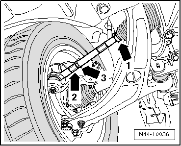
- Loosen bolts -1- for subframe -2- to body on both sides.
Adjusting the camber is limited by the subframe hole tolerances. If moving the subframe does not reach the specified value, then check the installation.
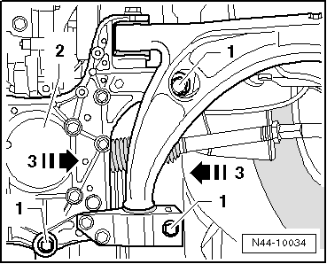
- Only specified value for camber can be adjusted by moving subframe -arrows 3-.
- Bolt on subframe to body with additional torque angle using new bolts.
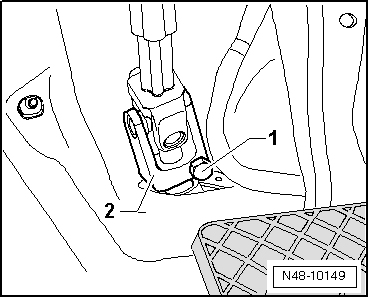
After sliding subframe and steering gear along with it as well, clearance between universal joint of steering column and cutout of bulkhead must be checked.
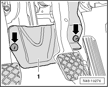
- Remove securing nuts -arrows- and remove foot well trim.
There must be at least 5 mm of clearance between universal joint -2- and cutout in bulkhead.
Tightening Specifications
| Component | Tightening Specification |
Mounting bracket to body
|
70 Nm + 180º |
Tightening Specifications, Subframe to Body
| Bolt | Tightening Specification |
M12 x 1.5 x 90
|
70 Nm + 180º |
M12 x 1.5 x 100
|
70 Nm + 180º |
M12 x 1.5 x 110
|
70 Nm + 90º |
Rear Axle Camber, Adjusting
Special tools and workshop equipment required
- Insert Tool - 18mm -T10179-
- Torque Wrench 1332 40-200Nm -VAG1332-
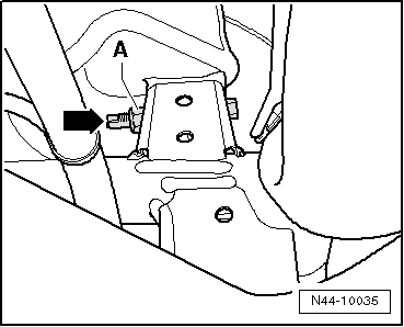
- Loosen nut -A- of threaded connection of upper transverse link at subframe.
- Adjust camber by turning hex of eccentric bolt -arrow-.
Note
The maximum adjustment range is 90º to left or right of center position.
- Tighten nut -A-.
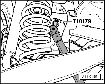
- To do so, use the Insert Tool - 18mm -T10179-.
When using Insert Tool - 18mm -T10179-, tighten nut to 80 Nm.
- After tightening the nut -A-, (Fig. N44-10035.
Tightening Specifications
| Component | Tightening Specification |
Upper transverse link to
subframe (vehicles with AWD)
|
95 Nm
|
Rear Axle Toe, Adjusting
Special tools and workshop equipment required
- Torque Wrench 1332 40-200Nm -VAG1332-
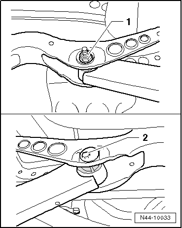
- Loosen nut -1-.
- Turn eccentric bolt -2- until the specified value has been reached.
- Now tighten nut again.
Tightening Specification
| Component | Tightening Specification |
Lower transverse link to
subframe
|
95 Nm |
Front Axle Toe, Adjusting
Special tools and workshop equipment required
- Torque Wrench 1332 40-200Nm -VAG1332-
- Torque Wrench 1332 Insert - Open Ring Wrench - 24mm -VAG1332/11-
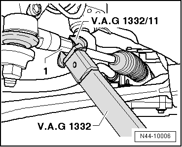
- Loosen lock nut -3-, counterhold at tie rod end -2- when doing so.
- Remove open spring clip -1- from boot.
- Adjust the toe by turning the left and/or right tie rod.
For this purpose, an open-end wrench can be placed on hex head of tie rod.
Be sure that boots are not twisted after turning tie rods!
Twisted boots wear out quickly.
- Tighten lock nut with Torque Wrench 1332 Insert - Open Ring Wrench - 24mm -VAG1332/11- while counterholding tie rod end -1-.
- Check toe value again.
Setting may change slightly after lock nut is tightened.
If the measured toe nevertheless lies within the tolerance, the adjustment is correct.
- Install the spring clamp on the boot.
Tightening Specifications
| Component | Tightening Specification |
| Tie rod end to tie rod | 70 Nm |
Basic Setting for Steering Angle Sensor -G85-
If steering wheel is offset, Basic Setting of Steering Angle Sensor -G85- must be checked! Perform a basic setting in Guided Fault Finding using Vehicle Diagnostic Tester.Use the GO TO in "function/component selection".
Vehicle Data Label
Currently the information on the data vehicle plate for each chassis installed is not available.
For information regarding each chassis installed, refer to ELSA/Vehicle Individual.
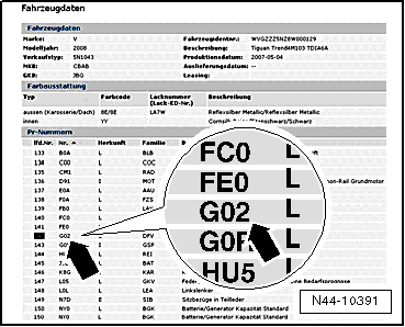
In this example the vehicle has basic suspension G02 -arrow- installed.
 Tire Pressure Monitoring System (TPMS) with Autolocation
General Information
Note
The Tire Pressure Monitoring System (TPMS) specified within this section
refers to the optional TPMS, which employs individual pressure sensors to
determine individual t ...
 Wheels and Tires
Vehicles with Tire Mobility Kit
The vehicles are equipped with a wheel repair kit.
The wheel repair kit is stored in the luggage compartment behind the right
trim panel. It contains a bottle of tire ...
See More:
Volkswagen Tiguan Service and Repair Manual > Workshop Equipment: Tools
Spray Can Filling Device -VAS6425-
Definition:
Spray Can Filling Device -VAS6425-
Product Description
The spray can filling device is a pneumatic, maintenance-free dispensing
device for filling spray cans with mixed base paint and top coats. The device is
suited for filling One-Part Fill-Clean ...
Volkswagen Tiguan Owners Manual
Volkswagen Tiguan Service and Repair Manual
- Body exterior
- Body Interior
- General Paint Information
- Paint
- Brake System
- Suspension, Wheels, Steering
- Wheel and Tire Guide
- Towing Guide
- Wheel and Tire Guide General Information
- Communication
- Electrical Equipment General Information
- Electrical Equipment from 06/2011
- Heating, Ventilation and Air Conditioning
- Refrigerant R134a Servicing
- 6-Speed Manual Transmission 02Q, OBB, and OFB
