Volkswagen Tiguan Service and Repair Manual: Tire Pressure Monitoring System (TPMS) with Autolocation
General Information
Note
- The Tire Pressure Monitoring System (TPMS) specified within this section refers to the optional TPMS, which employs individual pressure sensors to determine individual tire pressures.
- The base TPMS does not employ individual pressure sensors to determine individual tire pressures, but instead is an integral part of the Antilock Brake System (ABS). For more information on the ABS.
- The tire pressure monitoring system (TPMS) has running changes that replace the current tire pressure monitoring system (TPMS).
- The system currently uses sensors in the tires to report the air pressure on the Tire Pressure Monitoring Control Module -J502-.
- With the function "Autolocation", the system can display the tire pressures and warnings in the correct positions in the instrument cluster after a shorter distance.
- The "intelligent antenna" is a combination of the tire pressure monitoring control module and a central reception antenna.
- It is not necessary to perform a manual adapting after replacing the wheel electronics or after changing tires. The tire pressure monitoring system automatically recognized the tire pressure sensors and adapts them as soon as the vehicle drives off.
Additional information concerning the tire pressure monitoring system (TPMS) with Auto-location may be found in Self Study Program.
Overview - Tire Pressure Monitoring System
Note
- The Tire Pressure Monitoring System (TPMS) specified within this section refers to the optional TPMS, which employs individual pressure sensors to determine individual tire pressures.
- The base TPMS does not employ individual pressure sensors to determine individual tire pressures, but instead is an integral part of the Antilock Brake System (ABS). For more information on the ABS.
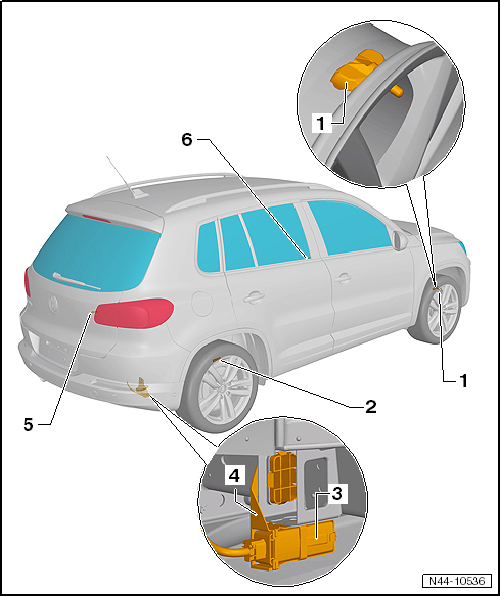
- Right Front Tire Pressure Monitoring Sensor -G223-
- Removing and Installing on vehicles after customer delivery.
- Removing and Installing on vehicles before customer delivery.
- Right Rear Tire Pressure Monitoring Sensor -G225-
- Removing and Installing on vehicles after customer delivery.
- Removing and Installing on vehicles before customer delivery.
- Tire Pressure Monitoring Control Module -J502-
- Removing and installing.
- Component location: on the right rear back panel
- Tire Pressure Monitoring Control Module -J502- Bracket
- Removing and installing.
- Left Rear Tire Pressure Monitoring Sensor -G224-
- Removing and installing on vehicles after customer delivery.
- Removing and installing on vehicles before customer delivery.
- Left Front Tire Pressure Monitoring Sensor -G222-
- Removing and installing on vehicles after customer delivery.
- Removing and installing on vehicles before customer delivery.
Overview - Tire Pressure Monitoring Sensor, Version 1
Note
- Version 1 was replaced by version 2.
- Only version 2 parts are available. Refer to the Parts Catalog.
- A mixed installation of version 1 and 2 is permitted.
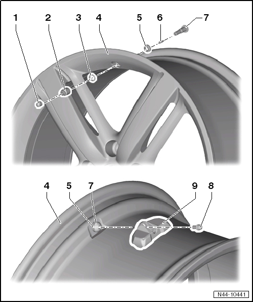
- Valve cap
- Nut
- 4 Nm
- Individual component of -item 7-
- Washer
- Individual component of -item 7-
- Disc Wheel
- Tire mounting.
- Seal
- Individual component of -item 7-
- Valve Insert
- Replace at every tire change
Note
Never use brass valve inserts (corrosion!) Only use nickel valve inserts (silver).
- Metal Valve
- Supplied complete as a service part
- Removing and installing.
- Bolt
- 4 Nm
- Individual component of -item 7-
- Tire Pressure Monitoring Sensor
- Left Front Tire Pressure Monitoring Sensor -G222-
- Right Front Tire Pressure Monitoring Sensor -G223-
- Left Rear Tire Pressure Monitoring Sensor -G224-
- Right Rear Tire Pressure Monitoring Sensor -G225-
- Removing and Installing on vehicles after customer delivery.
- Removing and Installing on vehicles before customer delivery.
Note
The tire pressure monitoring sensors expire after approximately 10 years.
Overview - Tire Pressure Monitoring Sensor, Version 2
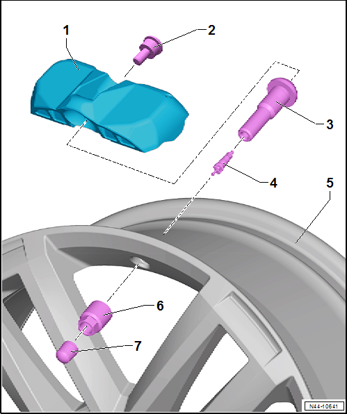
- Tire Pressure Monitoring Sensor
- Left Front Tire Pressure Monitoring Sensor -G222-
- Right Front Tire Pressure Monitoring Sensor -G223-
- Left Rear Tire Pressure Monitoring Sensor -G224-
- Right Rear Tire Pressure Monitoring Sensor -G225-
- Removing and installing.
- Bolt
- Flat head square head screw
- Is supplied as a replacement part with the tire pressure monitoring sensor. Refer to the Parts Catalog.
- Metal Valve
- Is supplied as a replacement part with the tire pressure monitoring sensor. Refer to the Parts Catalog.
- Valve Insert
- Replace at every tire change
- Rim
- Union Nut
- 4 Nm
- Do not counterhold on the metal valve when tightening
- A washer in the union nut causes the metal valve to be bolted down first to the Tire Pressure Monitoring Sensor when tightening. After the washer breaks, the Tire Pressure Monitoring Sensor will be bolted to the rim.
- Always replace if removed
- Valve Cap
Tire Pressure Sensor, Removing and Installing, Version 1, (Service Version)
Special tools and workshop equipment required
- Torque Wrench -VAG1410-
Note
- The Tire Pressure Monitoring System (TPMS) specified within this section refers to the optional TPMS, which employs individual pressure sensors to determine individual tire pressures.
- The base TPMS does not employ individual pressure sensors to determine individual tire pressures, but instead is an integral part of the Antilock Brake System (ABS). For more information on the ABS.
Perform the Following
Removing
Note
- Version 1 was replaced by version 2.
- Only version 2 parts are available. Refer to the Parts Catalog.
- A mixed installation of version 1 and 2 is permitted.
- Remove the tire from the disc wheel.
See Which Version Is Installed Before Starting Any Work.
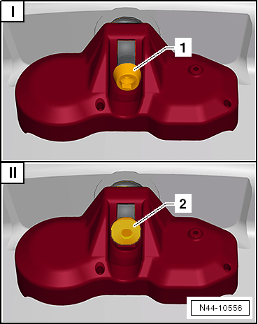
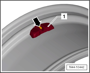
I - Service Version
The tire pressure monitoring sensor is attached to the valve with an inner TORX screw -1- on the Service version.
If the service version is installed, the following repair procedure must be used.
II - Production Version
The tire pressure monitoring sensor is attached to the valve with a square screw with a flat head -2- on vehicles before customer delivery.
If the production version is installed, the following repair procedure must be used.
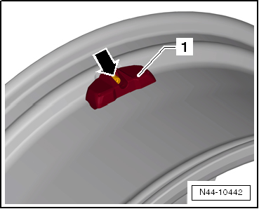
- Remove the screw -arrow- from the tire pressure monitoring sensor -1-.
- Counterhold metal valve using retainer (for example 2 mm spiral bore) while doing so.
Installing
Caution
Clean the valve opening before installing the Tire Pressure Monitoring Sensor.
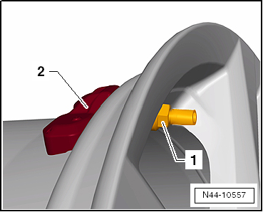
- Press the tire pressure monitoring sensor -1- onto the disc wheel (rim) and tighten -arrow-.
- Counterhold metal valve using retainer (for example 2 mm spiral bore) while doing so.
Note
- Visually check the valve after installing it and make sure it is tight. The tire pressure monitoring sensor -1- must not have any play when it is installed and it must touch the supports in the rim bed.
- Do not tighten the valve again to the tightening specification after it has been installed.
Tightening Specifications
| Component | Tightening Specification |
| Tire pressure monitoring sensor to metal valve | 4 Nm |
Tire Pressure Sensor, Removing and Installing, Version 1, (Production Version)
Special tools and workshop equipment required
- Torque Wrench -VAG1410-
Perform the Following
Removing
Note
- Version 1 was replaced by version 2.
- Only version 2 parts are available. Refer to the Parts Catalog.
- mixed installation of version 1 and 2 is permitted.
- Remove the tire from the disc wheel.
See which Version Is Installed before Starting Any Work.
I - Service Version
The tire pressure monitoring sensor is attached to the valve with an inner TORX screw -1- on the Service version.
If the service version is installed, the following repair procedure must be used → Anchor.
II - Production Version
The tire pressure monitoring sensor is attached to the valve with a square screw with a flat head -2- on vehicles before customer delivery.
If the production version is installed, the following repair procedure must be used → Anchor.
- Turn the nut -1- counter-clockwise until it is possible to remove the tire pressure sensor -2-.
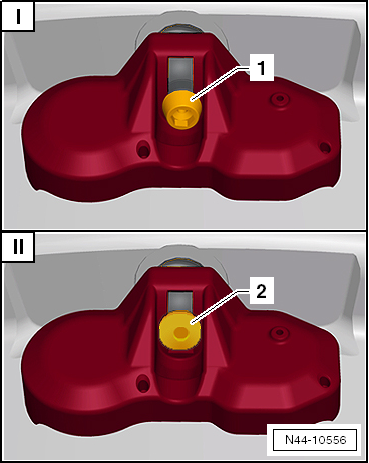
Note
- The whole valve turns when the nut it turned -1-.
- Both the tire pressure monitoring sensor and the metal valve must be replaced together. Refer to the Parts Catalog.
- Remove the metal valve.
Installing
Note
- Both the tire pressure monitoring sensor and the metal valve must be replaced together. Refer to the Parts Catalog.
- The new metal valve is available with a new screw as a replacement set.
- Install the metal valve.
Caution
Clean the valve opening before installing the Tire Pressure Monitoring Sensor.
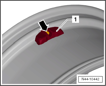
- Press the tire pressure monitoring sensor -1- onto the disk wheel (rim) and tighten the new screw -arrow-.
- Counterhold metal valve using retainer (for example 2 mm spiral bore) while doing so.
Note
- Visually check the valve after installing it and make sure it is tight. The tire pressure monitoring sensor -1- must not have any play when it is installed and it must touch the supports in the rim bed.
- Do not tighten the valve again to the tightening specification after it has been installed.
Tightening Specifications
| Component | Tightening Specification |
| Tire pressure monitoring sensor to metal valve | 4 Nm |
Tire Pressure Sensor, Removing and Installing, Version 2
Special tools and workshop equipment required
- Torque Wrench -VAG1410-
Removing
- Dismount the tire from the rim.
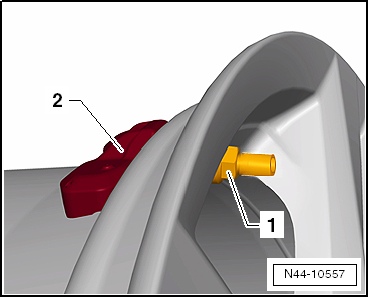
- Turn the nut -1- counter-clockwise until it is possible to remove the tire pressure monitoring sensor -2-.
Note
The whole valve turns when the nut it turned -1-.
Installing
Caution
- Always replace the entire metal valve.
- Clean the valve opening before installing the Tire Pressure Monitoring Sensor.
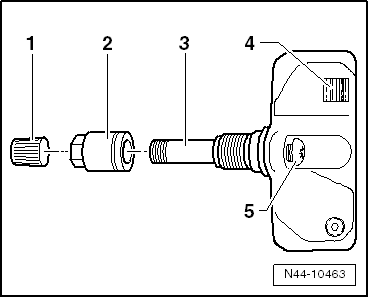
- Pre-mount the Tire Pressure Monitoring Sensor loosely with the square head screw -5- on the metal valve -3-.
Note
Make sure the metal valve is not screwed tightly onto the sensor.
- Insert the metal valve into the rim valve block.
Caution
- Do not counterhold on the metal valve when tightening
- A washer in the union nut -2- causes the metal valve to be bolted down first to the Tire Pressure Monitoring Sensor when tightening. After the washer breaks, the Tire Pressure Monitoring Sensor will be bolted to the rim.
- Screw the new union nut on the metal valve. At the same time the metal valve is turned and is attached to the Tire Pressure Monitoring Sensor.
- Tighten the union nut over the tangible break in the ruptured washer to the tightening specification.
- Install the tire on the rim.
Tightening Specifications
Refer to → Chapter "Overview - Tire Pressure Monitoring Sensor, Version 2"
Metal Valve, Removing and Installing
Special tools and workshop equipment required
- Torque Wrench -VAG1410-
Perform the Following
Removing
- Remove the Tire Pressure Monitoring Sensor.
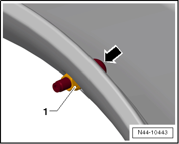
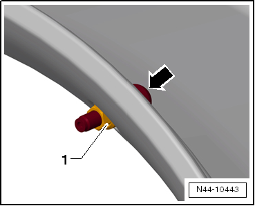
- Remove the nut -1- from the metal valve.
- Counterhold -arrow- the metal valve using a retainer (for example 2 mm spiral bore) while doing so.
Installing
Caution
Only apply the specified torque to tighten the nut for the metal valve. Tightening more is not permitted because it damages the seal.
- Tighten the nut -1- of the metal valve.
- Counterhold -arrow- the metal valve using a retainer (for example 2 mm spiral bore) while doing so.
- Install the Tire Pressure Monitoring Sensor.
Tightening Specifications
| Component | Tightening Specification |
| Hex nut to metal valve | 4 Nm |
Tire Pressure Monitoring Control Module -J502-, Removing and Installing
Component Location
The Tire Pressure Monitoring Control Module -J502- is installed on the rear right longitudinal member behind the wheel housing liner.
Perform the Following
Removing
- Switch off the ignition.
- Loosen the right rear wheel housing liner in the back and fold it forward.
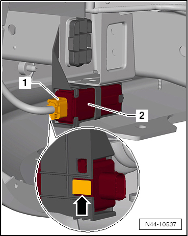
- Disconnect the connector -1-.
- Lightly press the tab -arrow- to the side and remove the Tire Pressure Monitoring Control Module -J502--2- from the mount.
Installing
Install in reverse order of removal.
Tire Pressure Monitoring Control Module -J502- Bracket, Removing and Installing
Perform the Following
Removing
- Remove the tire pressure monitoring control module -J502-.
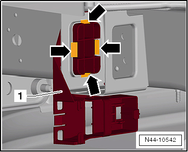
- Press the 4 tabs -arrows- inward and at the same time and remove the mount -1- from the plate.
Installing
Install in reverse order of removal. Note the following:
- All of the mount tabs -1- must be correctly tightened in order.
 Tire Pressure Monitoring System
General Information
Note
The base TPMS does not employ individual pressure sensors to determine
individual tire pressures, but instead is an integral part of the Antilock Brake
System (ABS). For mor ...
 Wheel Alignment
General Information and Special Tools
Special tools and workshop equipment required
Wheel Alignment Computer -VAG1813- or VW/Audi approved wheel alignment
devices
Brake Pedal Actuator -VAG1869/2- ...
See More:
Volkswagen Tiguan Service and Repair Manual > Wheel and Tire Guide General Information: Specifications for Retrofitting Wheel and Tire Combinations (Documents)
Legal Requirements
The manufacturer is granted general type approval for the whole vehicle
including all parts and for specific retrofitting (general type approval
according to 20 StVZO (Motor Vehicle Construction and Use Regulations or EU
type approval).
Retrofitting to wheels and tires can onl ...
Volkswagen Tiguan Owners Manual
Volkswagen Tiguan Service and Repair Manual
- Body exterior
- Body Interior
- General Paint Information
- Paint
- Brake System
- Suspension, Wheels, Steering
- Wheel and Tire Guide
- Towing Guide
- Wheel and Tire Guide General Information
- Communication
- Electrical Equipment General Information
- Electrical Equipment from 06/2011
- Heating, Ventilation and Air Conditioning
- Refrigerant R134a Servicing
- 6-Speed Manual Transmission 02Q, OBB, and OFB
