Volkswagen Tiguan Service and Repair Manual: Wiring
Vehicle Diagnostic Tester
All instructions and information on this chapter can be found in the "Electrical Equipment General Information" repair manual in ELSA.
Fuse Panel
Instrument Panel Fuse Panel
Instrument Panel Fuse Panel, Removing and Installing
Special tools and workshop equipment required
- Torque Wrench 1410 -VAG1410-
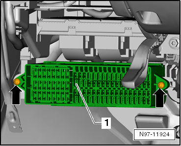
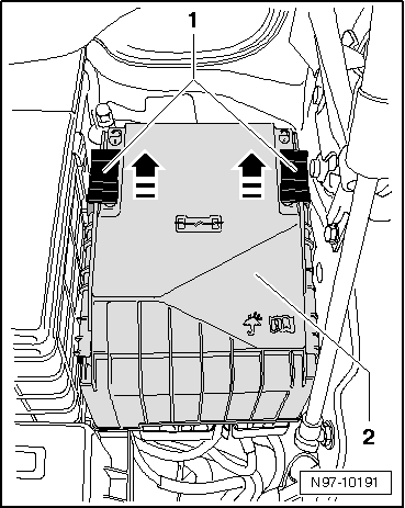
The fuse panel is located behind the storage compartment inside the driver footwell.
Caution
Always follow the procedure as described in the Repair Manual when disconnecting and connecting the battery.
Removing
- Switch off the ignition and all electrical consumers and remove the ignition key.
- Remove the trim inside the driver footwell.
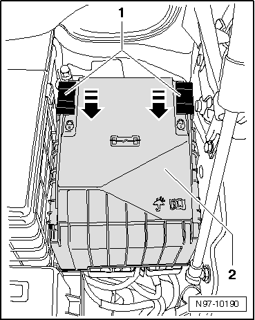
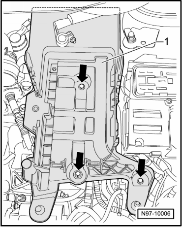
- Remove the screws -arrows- and pull the fuse panel -1- downward off the bracket.
Installing
Install in reverse order of removal. Note the following:
- Insert the right side of the fuse panel into the bracket.
- Then insert the left side of the fuse panel and tighten both screws.
- Tighten the screws to 4 Nm.
E-Box Fuse Panel
E-Box Fuse Panel, Removing and Installing
The description "Left Engine Compartment E-Box, Removing and Installing" describes the removal and installation of the fuse panel in the E-box.
Relay Panels
General Information
Component locations for relay panels:
- The instrument panel relay panel is clipped into a bracket above the vehicle electrical system control module.
- The relay panel on the vehicle electrical system control module is attached directly to the vehicle electrical system control module.
Instrument Panel Relay Panel, Removing and Installing
Caution
Always follow the procedure as described in the Repair Manual when disconnecting and connecting the battery.
Removing
- Disconnect the battery.
- Remove the trim on the driver side.
- Remove the Vehicle Electrical System Control Module -J519-.
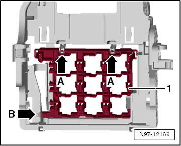
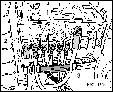
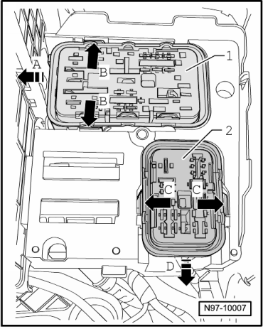
- Release the catches -arrows A- and remove the relay panel -1- downward. Pay attention to the wires still connected.
- Remove the relay panel -1- from the side guides -arrow B-.
- Disconnect all the connectors on the back of the relay panel -1-.
- Remove the relay panel -1- from the vehicle.
Installing
Install in reverse order of removal.
Relay Panel on Vehicle Electrical System Control Module, Removing and Installing
The relay panel on the vehicle electrical system control module is clipped under the vehicle electrical system control module and can be removed separately.
Removing
- Switch off the ignition and all electrical consumers and remove the ignition key.
- Remove the trim inside the driver footwell.
- Remove the fuse panel in the instrument panel.
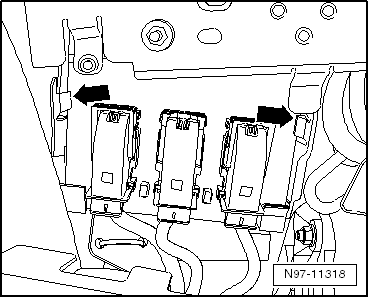
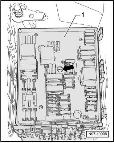
- Press both catches -arrows- and move the Vehicle Electrical System Control Module -J519- slightly downward.
- Pull the Vehicle Electrical System Control Module -J519- downward and opposite the direction of travel and remove it from the bracket.
- Turn the Vehicle Electrical System Control Module -J519- while paying attention to the connected wires.
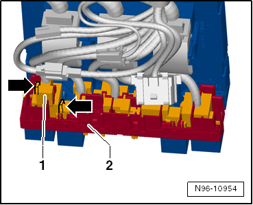
- Unlock both catches -arrows- and remove the relay panel -1- from the Vehicle Electrical System Control Module -J519--2- in the direction of -arrow-.
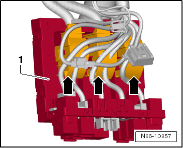
- Press the two release buttons on the relay connector -arrows- inward on the back of the relay panel and remove the relay connector -1- together with the relay from the relay panel -2-.
- Perform this procedure consecutively at all available relays and then remove the relay panel -2-.
Installing
Install in reverse order of removal. Note the following:
Note
Make sure the relay connectors are attached securely inside the relay panel and that the relay panel is attached securely to the vehicle electrical system control module.
E-Boxes
Left Engine Compartment E-Box
Left Engine Compartment E-Box, Removing and Installing
Special tools and workshop equipment required
- Torque Wrench 1410 -VAG1410-
Caution
Always follow the procedure as described in the Repair Manual when disconnecting and connecting the battery.
Removing
- Disconnect the battery.
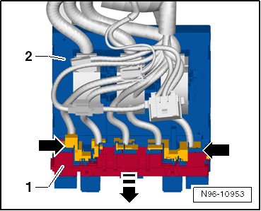
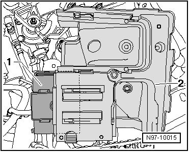
- Slide the securing brackets -1- in the direction of -arrow- and remove the cover of the E-box -2- upward.
Note
Mark the allocation of the connected wires to the connection points on the E-box.
Caution
- Electrical components that are protected by the fuse block can fail, for example, the electromechanical power steering
- The fuse block can get damaged when loosening the nut on the wiring connections.
- Replace the fuse block each time after loosening the connections.
- Unscrew the hex nuts -1-.
- Open the covers of the wire guides on the E-box -3- in the direction of -arrow-.
- Remove the wires from the connecting pins.
- Unclip the wires from the wire guides.
- Replace the fuse block -2- each time the hex nuts -1- are loosened.
Note
Following illustration shows "High" E-box version. Removing and installing the "Low" version is performed in the same way.
- Remove the central bolt -arrow- of the E-box -1-.
Note
Removing the central bolt -arrow- presses the E-box -1- up off the E-box bracket.
- Remove the E-box -1- upward from the E-box bracket.
Note
In order to be able to remove the flat terminal housing -1-, the air filter housing (only vehicles with a diesel engine), the battery, and the battery carrier must first be removed.
- If necessary, remove the air filter housing.
- Remove the battery.
- Unscrew the mounting bolts -arrows- of the battery carrier -1-.
- Remove the battery carrier -1- from the vehicle.
- Press the tabs on the E-box bracket apart -B arrows- and slide the flat terminal housing -1- sideways -arrow A- out of the E-box bracket.

Only vehicles with "High" E-box version:
- Press the tabs on the E-box bracket apart -arrows C- and slide the flat terminal housing -2- forward -arrow D- out of the E-box bracket.
All vehicles:
- Remove the nuts -arrows- of the E-box bracket -1-.
Note
It depends on the vehicle equipment whether an auxiliary relay panel is installed.
- Remove the E-box bracket -1- upward from the stud bolts. Be careful with the connected wires.
- Unclip the auxiliary relay panel -1- at
- Unclip the relay panel -1- at the side from the E-box bracket -2-.
- Remove the E-box bracket -2- from the vehicle.
Installing
Install in reverse order of removal. Note the following:
Caution
- Electrical components that are protected by the fuse block can fail, for example, the electromechanical power steering
- The fuse block can get damaged when loosening the nut on the wiring connections.
- Replace the fuse block each time after loosening the connections.
- Reconnect the wires -1- to the E-box according to the allocation marked during removal.
- Tighten the M5 nuts -1- (8 mm) to 4 Nm.
- Tighten the M6 nuts -1- (10 mm) to 6 Nm.
- Tighten the central bolt of the E-box to 9 Nm.

- Place the cover -2- onto the E-box and slide the securing brackets -1- in the direction of -arrow- until the cover -2- is engaged.
Note
Then check whether the cover -2- of the E-box is correctly engaged.
Control Modules
Vehicle Electrical System Control Module -J519-
General Information
The relay panel on the vehicle electrical system control module is clipped under the vehicle electrical system control module and can be removed separately. Relay Panel on Vehicle Electrical System Control Module, Removing and Installing.
Note
Additional information:
- Refer to Self Study Program; No 404; The Tiguan.
- Refer to → Wiring diagrams, Troubleshooting & Component locations
- Refer to Owner's Manual.
The Vehicle Electrical System Control Module -J519- controls the following functions in the vehicle:
- Electric load management
- Exterior light control
- Turn signal control
- Wipe/wash, windshield and rear window
- Headlamp Washer System
- Rain/Light Recognition Sensor
- Windshield and rear window defrosters
- Interior light control
- Terminal control
- Dimming, instrument illumination
- Footwell lamps
- Fuel pump supply
- Pre-energizing of the generator
- Horn
- Warning lamp
- Release control
- Controls central locking system
- Front and rear door control module activation
- Actuates rear lid unlock
- Actuates tank flap release
- Anti-theft alarm system activation
- Anti-theft immobilizer activation
- Activates the start authorization
- The following functions of the Vehicle Electrical System Control Module -J519- can be adapted.
- Adapts acoustic acknowledgement when unlocking
- Adapts acoustic acknowledgement when locking
- Adapts the blinking cycle during one-touch lane change signaling
- Adapting automatic unlocking when key is removed
- Adapts automatic locking at 15 km/h
- Adapt the sounder battery monitoring
- Adapts convenience locking confirmation
- Adapts coming home time
- Adapts leaving home time
- Adapts anti-theft alarm delay when opening driver door
- Adapts single door opening
- Interior monitoring sensitivity, adapting
- Inclination sensor sensitivity, adapting
- Deactivates factory mode
- Footwell Illumination Brightness, Adapting
- Adapt the Convenience feature for the window regulators
- Market version for the intelligent alarm horn, adapting
- Adapts the visual acknowledgment when locking
- Adapts the remote control key
- Remote Control Key, Checking
- Coding the wiper motor control module/deactivating the APP function
- Vehicle electrical system control module output diagnostic test
Note
It depends on the vehicle equipment whether the adaptations listed above can be performed.
Vehicle Electrical System Control Module -J519-, Removing and Installing
Note
- The relay panel on the vehicle electrical system control module is installed under the vehicle electrical system control module and can be removed.
- If the Vehicle Electrical System Control Module -J519- is being replaced, then the procedure "Coding vehicle electrical system control module" must always be performed to read out the codes stored in the module.
- Before coding the new Vehicle Electrical System Control Module -J519-, the factory mode/transport mode that was activated at the factory must be deactivated.
If the vehicle electrical system control module will be replaced:
- Perform "code vehicle electrical system control module".
Removing
- Switch off the ignition and all electrical consumers and remove the ignition key.
- Remove the relay panel from the vehicle electrical system control module.
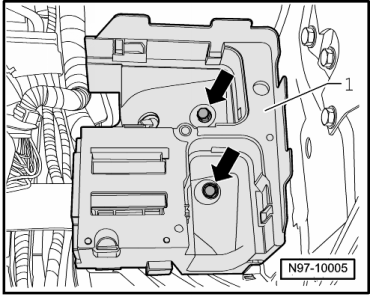
- Release and disconnect the three connectors -arrows-.
- Remove the vehicle electrical system control module -1-.
Installing
Install in reverse order of removal. Note the following:
- Insert the Vehicle Electrical System Control Module -J519- first with the back of the module into the bracket and then push it up until it audibly latches in the bracket.
If the Vehicle Electrical System Control Module -J519- was replaced:
- Deactivate factory mode.
- Code the Vehicle Electrical System Control Module -J519-.
Vehicle Electrical System Control Module -J519-, Coding
- Code the Vehicle Electrical System Control Module -J519- using the Vehicle Diagnostic Tester.
Vehicle Electrical System Control Module -J519-, Deactivating Factory Mode
If a new Vehicle Electrical System Control Module -J519- is installed, the factory mode that was activated at the factory must be deactivated. The vehicle cannot be locked or unlocked when factory mode is activated.
- Deactivate the Vehicle Electrical System Control Module -J519- factory mode using the Vehicle Diagnostic Tester.
Vehicle Electrical System Control Module -J519-, Adapting
The following functions can be adapted to the Vehicle Electrical System Control Module -J519-:
- Adapts acoustic acknowledgement when unlocking
- Adapts acoustic acknowledgement when locking
- Adapts the blinking cycle during one-touch lane change signaling
- Adapting automatic unlocking when key is removed
- Adapts automatic locking at 15 km/h
- Adapt the sounder battery monitoring
- Adapts convenience locking confirmation
- Adapts coming home time
- Adapts leaving home time
- Adapts anti-theft alarm delay when opening driver door
- Adapts single door opening
- Interior monitoring sensitivity, adapting
- Inclination sensor sensitivity, adapting
- Deactivates factory mode
- Footwell Illumination Brightness, Adapting
- Adapt the Convenience feature for the window regulators
- Market version for the intelligent alarm horn, adapting
- Adapts the visual acknowledgment when locking
- Adapts the remote control key
- Remote Control Key, Checking
- Coding the wiper motor control module/deactivating the APP function
- Vehicle electrical system control module output diagnostic test
- Connect the Vehicle Diagnostic Tester.
- Adapt the Vehicle Electrical System Control Module -J519- using the Vehicle Diagnostic Tester.
Data Bus On Board Diagnostic Interface -J533- (Gateway)
General Information
Component location Data Bus On Board Diagnostic Interface -J533-:
- Clipped into the heater bracket inside the driver footwell.
Note
Additional information:
- Refer to Self Study Program; No 404; The Tiguan.
- Refer to → Wiring diagrams, Troubleshooting & Component locations
- Refer to Owner's Manual.
The Data Bus On Board Diagnostic Interface -J533- (Gateway) is designed as a separate control module. It has the following tasks in the vehicle:
- Perform data exchange between CAN-Bus systems "Powertrain CAN-Bus", "Convenience CAN-Bus" and "Infotainment CAN-Bus"
- Transfers diagnostic data of CAN data bus systems onto K-wire and vice-versa, allowing the data from the Vehicle Diagnostic Tester to be used
Note
If the Data Bus On Board Diagnostic Interface -J533- is to be replaced, the work procedure to read out the codes stored in the module must always be performed.
Malfunction Recognition and Malfunction Indicator:
The Data Bus On Board Diagnostic Interface -J533- is equipped with OBD which assists with Fault Finding.
Use the Vehicle Diagnostic Tester in "Guided Fault Finding".
Data Bus On Board Diagnostic Interface -J533-, Replacing
- Replace the Data Bus On Board Diagnostic Interface -J533- using the Vehicle Diagnostic Tester.
- Data Bus On Board Diagnostic Interface -J533-, Removing and Installing.
Data Bus On Board Diagnostic Interface -J533-, Coding
- Code the Data Bus On Board Diagnostic Interface -J533- using the Vehicle Diagnostic Tester.
Data Bus On Board Diagnostic Interface -J533-, Removing and Installing
The Data Bus On Board Diagnostic Interface -J533- is clipped into the heater bracket inside the footwell on the driver side.
Removing
Note
If the Data Bus On Board Diagnostic Interface -J533- is to be replaced, the work procedure to read out the codes stored in the module must always be performed.
- Switch off the ignition and all electrical consumers and remove the ignition key.
- Remove the footwell vent on the driver side. Refer
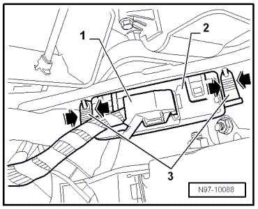
- Disconnect the connector -1-.
- Squeeze the pins -3- in the direction of -arrow- and remove the Data Bus On Board Diagnostic Interface -J533--2- from the holes.
- Remove the Data Bus On Board Diagnostic Interface -J533--2- from the vehicle.
Installing
Install in reverse order of removal.
Towing Recognition Control Module -J345-
General Information
- Special tools and workshop equipment required
- Trailer Socket Tester -VAS5800-
- Plug Socket Tester -VAS1537A-.
Note
Additional information: Refer to Self Study Program; No 404; The Tiguan.
Malfunction Recognition and Malfunction Indicator:
The Towing Recognition Control Module -J345- is equipped with OBD which assists Fault Finding.
Use the Vehicle Diagnostic Tester in "Guided Fault Finding".
The trailer socket can be checked with the Trailer Socket Tester -VAS5800- or the Power Outlet Tester -VAG1537/A-.
1) Power Outlet Tester -VAG1537/A- becomes too warm after a few minutes of use and switches off automatically. After a cooling off phase, the Power Socket Tester -VAS5800- functions normally again.
Towing Recognition Control Module -J345-, Removing and Installing
Removing
- Switch off the ignition and all electrical consumers and remove the ignition key.
- Remove the left side trim panel inside the luggage compartment.
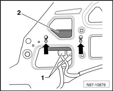
- Disconnect the connector -1-.
- Loosen the screws -arrows- and remove the Towing Recognition Control Module -J345--2-.
- Remove the Towing Recognition Control Module -J345--2- from the vehicle through the opening in the body.
Installing
Install in reverse order of removal. Note the following:
- Tighten the screws to 3.5 Nm.
Towing Recognition Control Module -J345-, Coding
- Code the Towing Recognition Control Module -J345- using the Vehicle Diagnostic Tester.
Wiring Harness and Connector Repairs
All instructions and information on this chapter can be found in the "Electrical Equipment General Information" repair manual. A link to this repair manual is currently not possible due to technical reasons. Refer to repair manual "Electrical Equipment General Information" in ELSA.
Special ToolsSpecial tools and workshop equipment required
- Torque Wrench 1410 -VAG1410-
- Plug Socket Tester -VAS1537A-
- Trailer Socket Tester -VAS5800-
Edition: K0059111621 - RF - 04/14/2015 - TMP
 Anti-Theft Alarm System
General Information
Note
Additional information: Refer to Owner's Manual.
General Description:
The anti-theft alarm system functions are integrated in the Vehicle
Electrical System Control Module -J5 ...

See More:
Volkswagen Tiguan Owners Manual > Exterior care and cleaning: Deicing door lock cylinders
Read and follow the introductory information and
safety information first⇒Introduction
to the subject Volkswagen recommends using only genuine Volkswagen deicer spray
with lubricating and anticorrosive properties to deice door lock cylinders.
Note
Lock deicers that contain grease solvent ...
Volkswagen Tiguan Owners Manual
Volkswagen Tiguan Service and Repair Manual
- Body exterior
- Body Interior
- General Paint Information
- Paint
- Brake System
- Suspension, Wheels, Steering
- Wheel and Tire Guide
- Towing Guide
- Wheel and Tire Guide General Information
- Communication
- Electrical Equipment General Information
- Electrical Equipment from 06/2011
- Heating, Ventilation and Air Conditioning
- Refrigerant R134a Servicing
- 6-Speed Manual Transmission 02Q, OBB, and OFB
