Volkswagen Tiguan Service and Repair Manual: Instrument Panel
Tools
Special tools and workshop equipment required
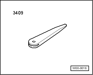
- Trim Removal Wedge -3409-
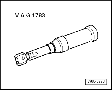
- Torque Wrench 1783 - 2-10Nm -VAG1783-
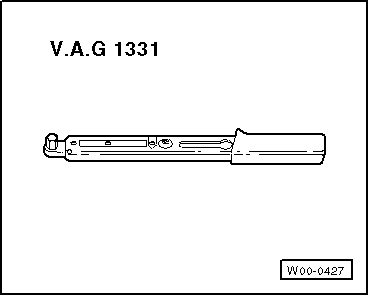
- Torque Wrench 1331 5-50Nm -VAG1331-
Instrument Panel, Removing and Installing
Removing
- Disconnect the vehicle battery.
- Remove the steering column trim gap cover.
Note
It is not necessary to remove any more parts from the steering column trim panel.
- Remove the instrument cluster.
- Remove the instrument panel side covers.
- Remove the upper trim panels of the A-pillars.
- Remove the glove compartment.
- Remove the center console cover.
- Remove the trim on both sides of the footwell.
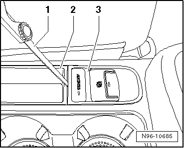
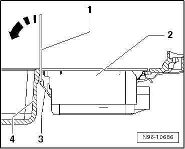
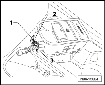
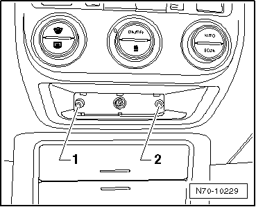
- Carefully guide a feeler gauge with 0.6 mm thickness -1- in the gap between the center console -2- and button module -3-.
- Straighten the feeler gauge vertically and push it 10 mm deep in between the button module and the center console.
Note
The vertical inserting of the feeler gauge makes sure that the lock button reaches the outside. After 10 mm insertion depth the point of the feeler gauge contacts the lock button offset noticeably.

- Tip the feeler gauge -1- in the direction of the -arrow- to push the lock button -3-. Pry out the button module -2- at the same time upward from the rear of the center console -4-.

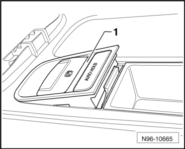
- Remove the button module -1- while paying attention to the wires that are still connected, upward from the center console.
- Remove the primary connector -1- push the lock button -2- and release and remove the connector -3-.
- Remove the primary connector -1- push the lock button -2- and release and remove the connector -3-.
Vehicles with a Center Console without a Center Armrest
- Remove the center console, without center armrest.
Vehicles with a Center Console with a Center Armrest
- Remove the DVD player if equipped.
- Remove the CD changer if equipped.
- If equipped remove the "Apple""IPod player" baseplate.
- Remove the storage compartment with USB connection, if present.
- Remove the multimedia system control module, if present.
Vehicles with Multimedia System
- Remove the multimedia system control head.
Vehicles with Converter with Socket, 12 V-230 V -U13-
- Remove the Converter with Socket, 12 V-230 V - U13-.
- Remove the center console trim.
- Remove the center console, with center armrest.

All Vehicles
- Remove the Light Switch -E1-.
- Remove right trim panel on driver side.
- Remove the telephone holder.
- Remove the center instrument panel trim.
- Remove the heat and A/C controls trim.
Vehicles Equipped with a Radio System or a Radio Navigation System
- Remove the radio.
"Climatic" A/C System with Manual Control
- Remove the "Climatic" heater and A/C controls.
"Climatronic" A/C System with Automatic Control
- Remove the Front A/C Display Control Head -E87- and Climatronic Control Module -J255-.
Vehicles without A/C
- Remove the heating and ventilation controls.
All Vehicles
- Remove the lower trim on the instrument panel.
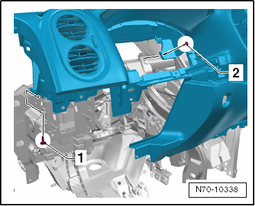
- Remove the bolt under the left vent -1- (2.5 +- 0.5 Nm).
- Remove the instrument cluster bolt -2- (2.5 +- 0.5 Nm).
- Remove the bolt under the right vent -1- (2.5 +- 0.5 Nm).
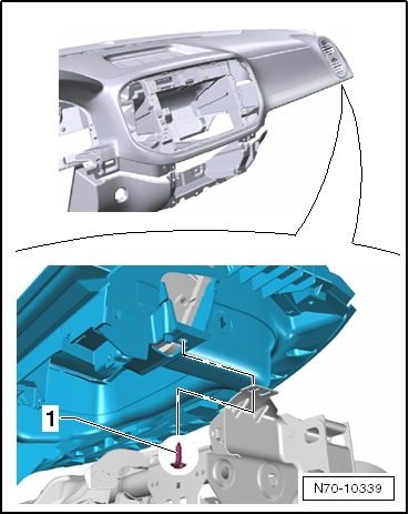
- Remove two bolts -1- (2.5 +- 0.5 Nm) above the tunnel.

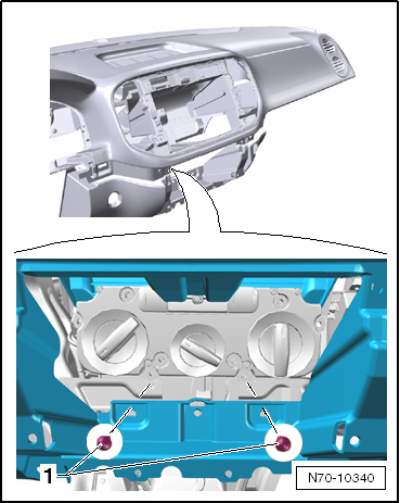
- Remove two bolts -1- (9 Nm) from the front passenger airbag.
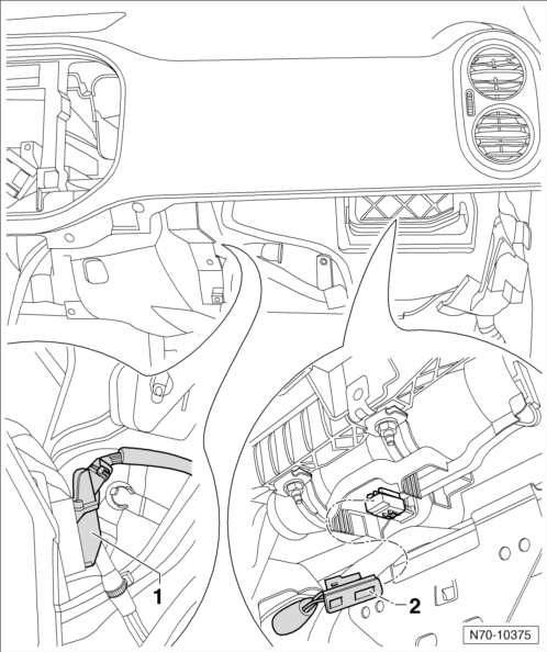
- Disconnect the connector -1- from the Headlamp Range Control Module -J431-.
- Disconnect the connector -2- from the front passenger airbag.
- Disconnect the connector -1- from the Left Vent Temperature Sensor -G150-, if equipped.
- Lift the instrument panel slightly until the side centering tabs -2- are above the mounting plate -3-.
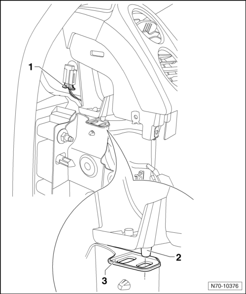
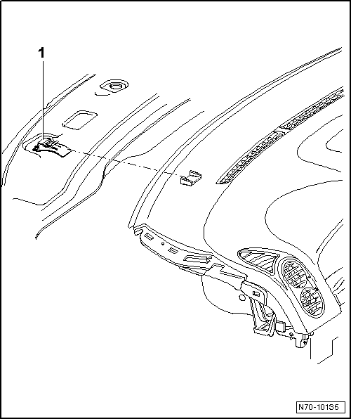
- Pull instrument panel out of mounts -1- in windshield transition area.
- Depending on vehicle equipment, disconnect the corresponding wiring harnesses and remove the instrument panel from the vehicle with a second technician.
Installing
- Install in reverse order of removal.
Note
When installing the instrument panel, make sure that instrument panel is placed with exact fit into mounts -1-.

Assembly Carrier, Removing and Installing
Draw sketches or take pictures when loosening or removing and installing wires. This ensures installation is the same as the original.
Removing
- Disconnect the vehicle battery.
- Remove driver side airbag unit:
- Through 05/2011.
- From 06/2011.
- Remove the driver side airbag unit
- Remove the steering wheel.
- Remove the steering column trim panel.
- Remove the Steering Column Electronics Control Module - J527-.
- Remove the Airbag Spiral Spring/Return Spring with Slip Ring -F138-.
- Remove the Steering Angle Sensor -G85-.
- Remove the Turn Signal Switch -E2-.
- Remove the Windshield Wiper Switch -E-.
- Remove the instrument cluster.
- Remove the instrument panel side covers.
- Remove the upper trim panels of the A-pillars.
- Remove the hood release lever.
- Remove the lower trim on the A-pillar on the driver side.
- Remove the glove compartment.
- Remove the center console cover.
- Remove the trim on both sides of the footwell.

- Carefully guide a feeler gauge with 0.6 mm thickness -1- in the gap between the center console -2- and button module -3-.
- Straighten the feeler gauge vertically and push it 10 mm deep in between the button module and the center console.
Note
The vertical inserting of the feeler gauge makes sure that the lock button reaches the outside. After 10 mm insertion depth the point of the feeler gauge contacts the lock button offset noticeably.
- Tip the feeler gauge -1- in the direction of the -arrow- to push the lock button -3-. Pry out the button module -2- at the same time upward from the rear of the center console -4-.
- Remove the button module -1- while paying attention to the wires that are still connected, upward from the center console.
- Remove the primary connector -1- push the lock button -2- and release and remove the connector -3-.
- Remove the button module from the vehicle.
Vehicles with a Center Console Without a Center Armrest
- Remove the center console, without center armrest
Vehicles with a Center Console with a Center Armrest
- Remove the DVD player if equipped.
- Remove the CD changer if equipped.
- If equipped remove the "Apple""IPod player" baseplate.
- Remove the storage compartment with USB connection, if present.
- Remove the multimedia system control module, if present.
Vehicles with Multimedia System
- Remove the multimedia system control head.
Vehicles with Converter with Socket, 12 V-230 V -U13-
- Remove the Converter with Socket, 12 V-230 V - U13-.
- Remove the center console trim.
- Remove the center console, with center armrest.
All Vehicles
- Remove the Light Switch -E1-.
- Remove right trim panel on driver side.
- Remove the telephone holder.
- Remove the center instrument panel trim.
- Remove the heat and A/C controls trim.
Vehicles Equipped with a Radio System or a Radio Navigation System
- Remove the radio.
"Climatic" A/C System with Manual Control
- Remove the "Climatic" heater and A/C controls.
"Climatronic" A/C System with Automatic Control
- Remove the Front A/C Display Control Head -E87- and Climatronic Control Module -J255-.
Vehicles without A/C
- Remove the heating and ventilation controls.
All Vehicles
- Remove the lower trim on the instrument panel.
- Remove the instrument panel.
- Remove the wiper arms.
- Remove the left plenum chamber cover.

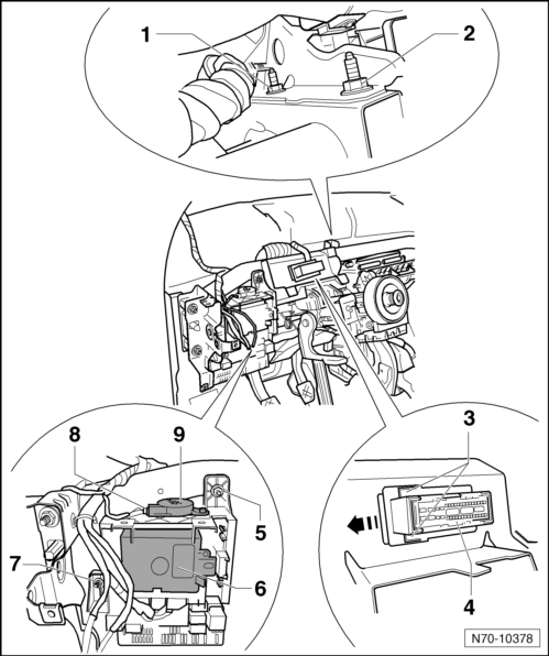
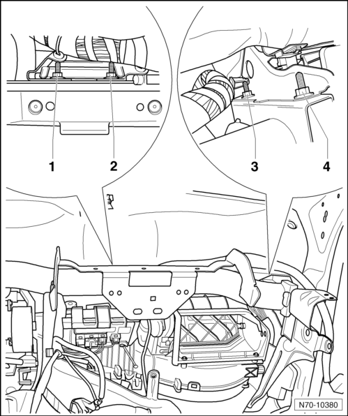
- Remove the plenum chamber bolt -1- (20 Nm).
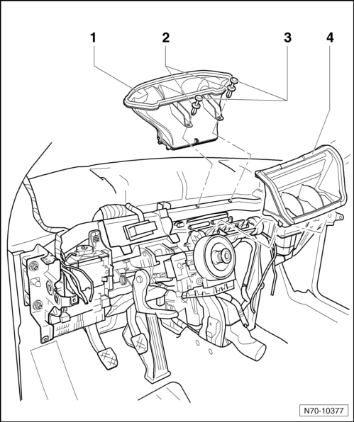
- Remove the two locking pins -3- and then remove the two expanding rivets -2-.
- Remove the intermediate pieces -1- and -4- from the A/C unit.
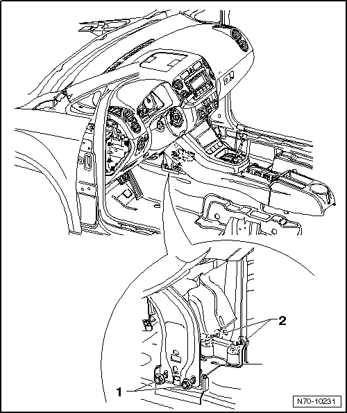
- In the direction of travel, remove the nuts -1- and -2- from the assembly carrier (8 Nm).
- Slightly lift the two straps -3- and push the instrument panel connector -4- to the left -arrow-.
- Pull the connector out of the opening in the assembly carrier.
Note
When removing the assembly carrier, pay close attention to the position of the electrical wires and their mountings; if necessary make a sketch or take photographs.
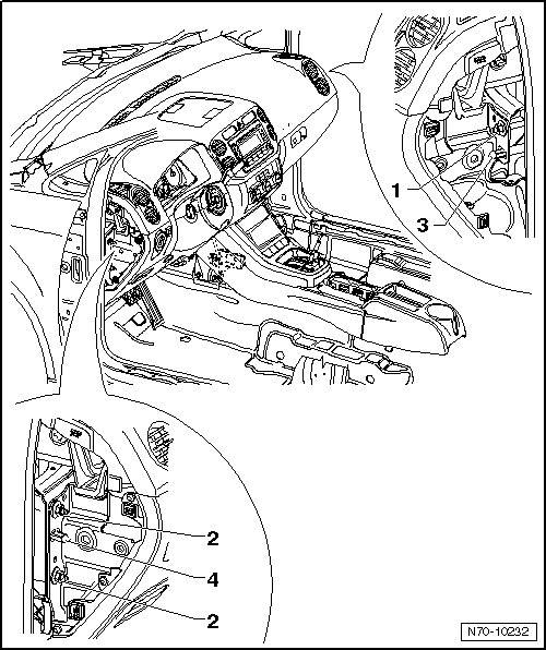
- Remove the nut -5- (4.5 Nm).
- Press the side retaining tabs on the Parallel Parking Assistance Control Module -J791--6- outward and remove the control module from the relay carrier.
- Remove the nut -7- (4.5 Nm).
- Disconnect the harness connector -8- from the Front Parking Aid Warning Buzzer -H22--9-.
- Remove the relay carrier from the assembly carrier.
- Remove the left footwell vent.
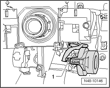
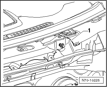
- Disconnect the wiring harness -1- from the Anti-Theft Immobilizer Reader Coil -D2-.
- Disconnect the steering column from the assembly carrier.
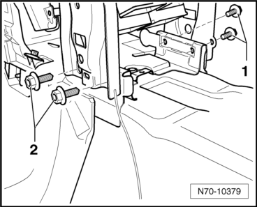
- Remove the right and left bolts -1- and -2- (20 Nm).
- In the direction of travel, remove the nuts -1- and -2- from the assembly carrier (8 Nm).
- In the direction of travel, remove the nuts -3- and -4- from the assembly carrier (8 Nm).
Note
Using a scriber, mark the height and side position of the assembly carrier in the vehicle around the nuts -1- and -2-.
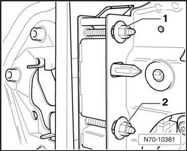
- Remove the two nuts -1- and -2- (20 Nm) on the driver side.
Note
Using a scriber, mark the height and side position of the assembly carrier in the vehicle around the nut -2-.
- Remove the nut -2- (20 Nm) on the front passenger side.
- Remove the harness connector retainers from the assembly carrier, depending on vehicle equipment.
Note
When removing the assembly carrier, pay close attention to the position of the electrical wires and their mountings; if necessary make a sketch or take photographs.
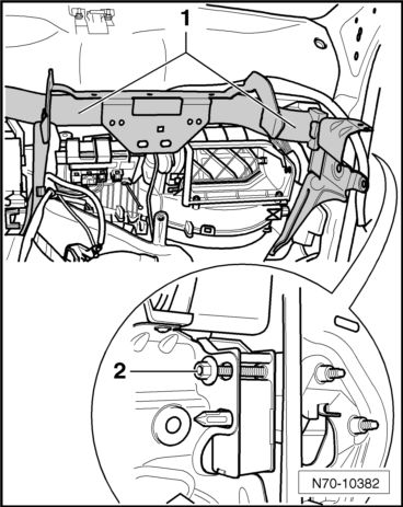
- With a second technician, carefully remove the assembly carrier -1- from the vehicle.
Installing
- Install in reverse order of removal.
Note
Before installing the assembly carrier, line it up with the markings made before it was removed.
Instrument Panel, Aligning in Vehicle
It is not necessary to change instrument panel position to increase horizontal gap between door trim and instrument panel.
- Hold an appropriately thick cloth at left edge of instrument panel and close the door.
In this way, the door trim panel engages closer to door and the gap between door trim and instrument panel increases appropriately. Thus, it is not necessary to align the instrument panel.
Note
Do the same on the front passenger side.
Instrument Panel, Aligning
Instrument panel can be aligned in height and diagonally to the direction of travel.
- Remove the wiper arms.
- Remove the left plenum chamber cover.
- Remove the instrument panel side covers.
- Remove the heat and A/C controls trim.
- Loosen the bolts -1- and -2- under the heater and air conditioning controls 2 to 3 turns (2.5 +- 0.5 Nm).
- Remove the trim on both sides of the footwell.
- Loosen the bolt -1- in the plenum chamber 2 to 3 turns (20 Nm).
Note
The Golf Plus is shown in the illustration; this does not affect the work being performed.
- Loosen the two bolts -1- and -2- in the tunnel area 2 to 3 turns (20 Nm).
Note
The Golf Plus is shown in the illustration; this does not affect the work being performed.
- Loosen the nut -1- on right side 2 or 3 turns (20 Nm).
- Loosen the two nuts -2- on the left side 2 to 3 turns (20 Nm).
Instrument Panel Height, Aligning
Note
- Instrument panel height is set using eccentric screws -3- and -4-.
- In the zero position, the longer eccentric surface faces toward outside of vehicle.
- The eccentric must not be turned more than +-90º out of zero position.
Adjust the desired instrument panel height using eccentric screws -4- and -3-.
Align the instrument panel diagonally to the direction of travel.
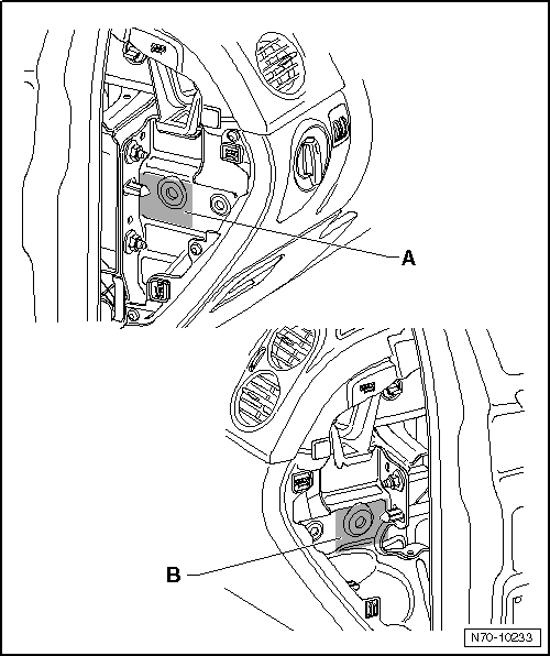
Caution
When adjusting, only the marked surfaces on the instrument panel can be loaded to prevent damage to the vehicle.
- Push the instrument panel, inside the marked surfaces -A- and -B-, into the desired position.
After aligning in vehicle, tighten the instrument panel to the specified torques.
Installation of removed components is reverse of removal.
 Interior Trim
...
 Door Trim Panels
Tools
Required Special Tools and Testing Equipment
Trim Removal Wedge -3409-
Trim Release Lever - Wedge -T10039/1-
Torque Wrench 1783 - 2-10Nm -VAG1783-
Front Door Trim Panel, Removing and ...
See More:
Volkswagen Tiguan Owners Manual > Sun protection: Windshield made of heat-insulating glass
Fig. 85 Heat-reflective windshield with
communications window (blue shaded area).
Read and follow the introductory information and
safety information first⇒Introduction
to the subject Windshields made of insulating glass have a transparent metallic
infrared-reflecting coating. There is ...
Volkswagen Tiguan Owners Manual
Volkswagen Tiguan Service and Repair Manual
- Body exterior
- Body Interior
- General Paint Information
- Paint
- Brake System
- Suspension, Wheels, Steering
- Wheel and Tire Guide
- Towing Guide
- Wheel and Tire Guide General Information
- Communication
- Electrical Equipment General Information
- Electrical Equipment from 06/2011
- Heating, Ventilation and Air Conditioning
- Refrigerant R134a Servicing
- 6-Speed Manual Transmission 02Q, OBB, and OFB
