Volkswagen Tiguan Service and Repair Manual: Electrical Components Not on Refrigerant Circuit
A/C Programmer -J127-
This programmer switches the refrigerant flow direction through the second evaporator if the temperature on the cooling fins on the second evaporator lowers to the freezing point for water (icing protection).
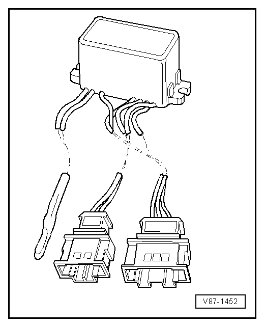
Coolant Fan Control Module -J293-
Note
There are different construction styles.
This control module switches on and off the A/C clutch and therefore the A/C compressor. It switches the coolant fan and calculates the pressure in the refrigerant circuit on vehicles with a High Pressure Sensor -G65- or A/C Pressure/Temperature Sensor -G395-.
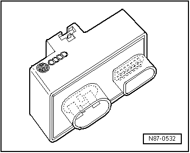
Coolant Fan Control Module -J293-
Note
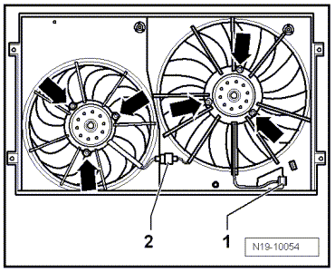
Available in different construction styles, some installed on coolant fan -arrows-.
This control module switches on and off the A/C clutch and therefore the A/C compressor. It switches the coolant fan and calculates the pressure in the refrigerant circuit on vehicles with a High Pressure Sensor -G65- or A/C Pressure/Temperature Sensor -G395-.
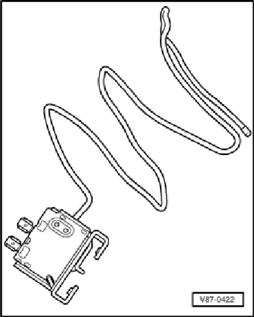
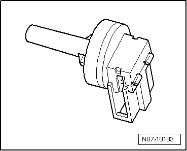
A/C Evaporator Temperature Switch -E33-
Function:
The A/C Evaporator Temperature Switch -E33- determines the temperature between the evaporator cooling fans. It prevents the possibility of ice building up between the evaporator cooling fans because the current entry to the condenser magnetic clutch is interrupted when the temperature on the cooling fins lowers to the freezing point for humidity.
The insertion depth of the feeler tube is marked or indicated in the repair manual.
Note
Installed on VW vehicles with the A/C compressor drive above the ribbed belt
Evaporator Vent Temperature Sensor -G263- or Evaporator Temperature Sensor -G308-
Function:
The Evaporator Vent Temperature Sensor -G263- or Evaporator Temperature Sensor -G308- determines the temperature behind the evaporator. This value goes to the air conditioning control module and serves as a reference signal for regulating the A/C compressor. This prevents the evaporator from icing up.
Refrigerant Circuit Pressures and Temperatures
WARNING
When performing work on refrigerant circuit, observe all generally applicable safety precautions and pressure vessel regulations.The pressures and temperatures in the refrigerant circuit depend on the current operating conditions (such as engine RPM, coolant fan level 1, 2 or 3, engine temperature, A/C compressor on or off) as well as on the effects of outside influences (such as outside temperature, humidity, desired cooling output).
In vehicles with A/C Compressor Regulator Valve -N280-, the pressure is modified on the low pressure side by the valve.For this reason, values indicated in the following table are valid only as reference points. They are attained at an engine speed of 1,500 to 2,000 RPM and an ambient temperature of 20 ºC (68 ºF) after about 20 minutes.
The connections provided for measuring pressure for the manometer battery are located in the vehicle-specific refrigerant circuit.At 20 ºC (68 ºF) with the engine not running, the pressure in the refrigerant circuit is 4.7 bar (68.17 psi).
Refrigerant Circuit with Expansion Valve
- Low pressure side of refrigerant circuit.
- High pressure side of refrigerant circuit.
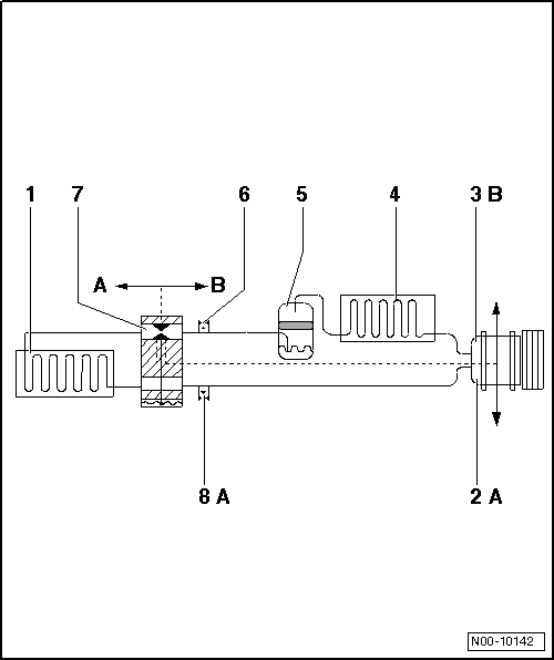
| Component | Aggregate State of Refrigerant | Pressure bar (psi) Positive Pressure | Temperature in Degrees Celsius (Fahrenheit) |
| -1- Evaporator, from input to output | Vapor | Approximately 1.2 (17.4) | Approximately -7 (20) |
| (Approximately 1.8 (26.1) ) | Approximately -1 (30) | ||
| -2- A/C compressor A-side | Gas | Approximately 1.2 (17.4) | Approximately -1 (30) |
| (Approximately 1.8 (26.1) ) | Approximately -1 (30) | ||
| -3- A/C compressor B-side | Gas | Approximately 14 (203.1) | Approximately 65 (149) |
| -4- Condenser | Gas, vapor, fluid | Approximately 14 (203.1) | Approximately 55 (131) at outlet |
| -5- Receiver | Fluid | Approximately 14 (203.1) | Approximately 55 (131) |
| -6- Extraction and filling valve, B-side | Fluid | Approximately 14 (203.1) | Approximately 55 (131) |
| -7- Expansion valve | Fluid, released as vapor | Approximately 14 (203.1) | Approximately 55 (131), reduced to -7 (20) |
| -8- Extraction and filling valve, A-side | Gas | Approximately 1.2 (17.4) | Approximately -7 (20) |
| (Approximately 1.8 (26.1) ) | Approximately -1 (30) |
1) Pressure in refrigerant circuits is maintained at approximately 2 bar (29 psi), regulated by A/C compressor, even though heat transfer changes and engine speeds vary. However, this applies only within the performance range of the A/C compressor; if the performance limits of the A/C compressor are exceeded, the pressure increases.
2) Within the control range of the A/C compressor, temperature in the refrigerant circuits is maintained, regulated by A/C compressor, even though heat transfer changes and engine speeds vary. However, this applies only within the performance range of the A/C compressor; if the performance limits of the A/C compressor are exceeded, the temperature increases.
3) Measured values for A/C systems with two evaporators
Note
- A/C compressors which do not regulate their performance are switched off by the respective control module via the A/C Compressor Regulator Valve -N280- at an evaporator temperature below 0 ºC (32 ºF).
- In vehicles with A/C Compressor Regulator Valve -N280-, the pressure is modified on the low pressure side by the valve.
Refrigerant Circuit with Restrictor and Reservoir
Arrows point in direction of refrigerant flow.
- Low pressure side of refrigerant circuit.
- High pressure side of refrigerant circuit.
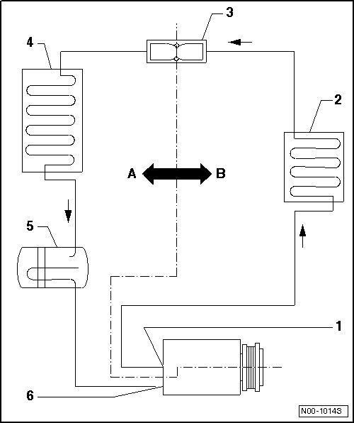
| Component | Aggregate state of refrigerant | Pressure bar (psi) positive pressure | Temperature in degrees Celsius (Fahrenheit) |
| -1- A/C compressor B-side | Gas | up to 20 (290 psi) | up to 70 (158) |
| -2- Condenser | From gas to vapor to fluid | up to 20 (290 psi) | up to 70 (158) |
| -3- Restrictor | From fluid to vapor | B-side to 20 (290 psi), A-side greater than 1.5 (21.8 psi) | B-side up to 60 (140 psi), A-side warmer than -4 (25) |
| -4- Evaporator | From vapor to gas | Greater than 1.5 (21.8 psi) | Warmer than -4 (25) |
| -5- Reservoir | Gas | ||
| -6- A/C compressor A-side | Gas |
Pressures on A-side are maintained at approximately 2 bar (29 psi) by "regulating" A/C compressor also at various engine speeds. However, this applies only within the performance range of the A/C compressor; if the performance limits of the A/C compressor are exceeded.
Note
In vehicles with A/C Compressor Regulator Valve -N280-, the pressure is modified on the low pressure side by the valve.
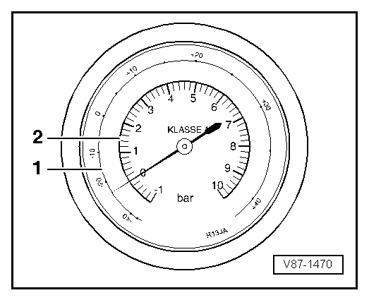
Pressure Gauge, Tests and Measurements
Indicators on pressure gauge
- Temperature scale for refrigerant R134a CF3-CH2F or CH2F-CF3.
- Pressure scale
The pressure gauge may have one or more temperature scales next to the pressure scale. The R134a scale values are allocated respectively in the vapor pressure table. Since various refrigerants create different vapor pressures at the same temperature, each temperature scale is identified for the respective refrigerant.
Pressure Gauge Uses
a - Pressure and temperature measurement at refrigerant circuit
- High pressure gauge measures pressure and temperature, which expand uniformly from outlet of A/C compressor via the condenser up to constriction (restrictor, or expansion valve) with A/C system switched on.
- Low pressure gauge measures pressure and temperature, which expand uniformly from constriction (restrictor, or expansion valve) via evaporator up to input of A/C compressor with A/C system switched on.
Note
The relationship between pressure and temperature indicated on the gauges only exists in a refrigerant circuit that contains liquid or vapor, but not gas. In a gaseous state, the temperature is approximately 10 ºC (50 ºF) to 30 ºC (86 ºF) higher than indicated on the gauge.
b - Verification of refrigerant in a closed container
Refrigerant R134a is present in a closed vessel or in a refrigerant circuit when the temperature indicator on the gauge matches the refrigerant temperature (the temperature of standing fluid is equal to the outside temperature).
A closed vessel or a refrigerant circuit that has been switched off is empty when the temperature indicated on the gauge is below the temperature of the refrigerant.
Note
The relationship between pressure and temperature indicated on the gauges no longer applies if no liquid is present and the pressure is built up solely by gas.
A/C Service and Recycling Units
Extraction System Group Classifications
At this time, A/C service units for extracting, cleaning and filling refrigerant for motor vehicle A/C systems are available from various manufacturers.Group 3:
Mobile extraction and charging systems for filling compressed-gas vessels permanently connected to the system.The refrigerant or refrigerant/oil mixture is transferred to compressed gas vessels which are permanently connected to the mobile systems. In accordance with 3 Para. 5 No. 3 of pressure vessel regulations, compressed-gas vessels are classified as pressure vessels in this case.
The charging systems require:- no permit
- no expert testing as the gas is transferred to compressed-gas vessels which are classed as being pressure vessels. (Systems used for transfer from these pressure vessels to compressed-gas vessels for supplying to third parties do require a permit and are subject to mandatory testing).
Note
The A/C service and recycling units used in motor vehicle workshops are extraction and charging systems not requiring a permit (Group "3") but which are only to be operated by qualified personnel. Instructions for unit operation and maintenance can be found in the relevant manufacturer's documentation.
Charging Systems not Requiring a Permit
At this time, A/C service units for extracting, cleaning and filling refrigerant for motor vehicle A/C systems are available from various manufacturers.Charging systems not requiring a permit are ones used for transferring compressed gases to mobile compressed-gas vessels for internal use only.
Note:Some A/C service units are charging systems not requiring a permit. When working with such equipment, the refrigerant is not transferred to mobile compressed-gas vessels, but rather into a permanently installed charging cylinder with visible level gauge and float switch.
Recommendation:It is advisable to use a portable cylinder with visible level gauge and pressure relief valve for surplus refrigerant for internal use.
Observe the different technical regulations for handling and filling compressed gases in other compressed-gas vessels (for example RGS 400, TRGS 402, TRGS 407, TRGS 510, TRBS 3145 / TRGS 725).Refrigerant Circuit Repair Information
WARNING
When performing work on refrigerant circuit, observe all generally applicable safety precautions and pressure vessel regulations.
Caution
Non-approved tools or materials such as leak sealing additives can cause damage or malfunctions in the system.
Only use tools and materials approved by the manufacturer.
The warranty is voided if non-approved tools or materials are used.
Special tools and accessories:
The performance of proper workmanlike repairs on an air conditioning system:
- Requires the use of special tools and materials as listed in.
- Requires compliance with the basic instructions for use of leak detectors.
- Requires expert knowledge.
Note
Releasing refrigerant into the environment is not permitted (punishable by law).
 Switches and Sensors on Refrigerant Circuit and Connections
A/C Refrigerant High Pressure Switch -F23-
Note
For switching pressures, removing and installing switches and switch
arrangement and version, see vehicle-specific refrigerant circuit.
Function:
Swit ...
 Laws and Regulations
Laws and Regulations
Note
The laws and regulations listed below are applicable in Germany.
Different or additional laws and regulations may apply in other countries.
Addresses in other countries ...
See More:
Volkswagen Tiguan Owners Manual > Starting and stopping the engine: Stopping the engine
Read and follow the introductory information and
safety information first⇒Introduction
to the subject
Please perform these steps only in the
order listed.
Vehicles without Keyless Access
Vehicles with Keyless Access
1.
Bri ...
Volkswagen Tiguan Owners Manual
Volkswagen Tiguan Service and Repair Manual
- Body exterior
- Body Interior
- General Paint Information
- Paint
- Brake System
- Suspension, Wheels, Steering
- Wheel and Tire Guide
- Towing Guide
- Wheel and Tire Guide General Information
- Communication
- Electrical Equipment General Information
- Electrical Equipment from 06/2011
- Heating, Ventilation and Air Conditioning
- Refrigerant R134a Servicing
- 6-Speed Manual Transmission 02Q, OBB, and OFB
