Volkswagen Tiguan Service and Repair Manual: General Information
Caution
The removal and installation of individual steering column switch components must be done in a specified sequence.
WARNING
Before working on electronic system and removing the steering wheel the following conditions must be met:
The technician must discharge static electricity. This is accomplished by touching grounded metal like, for example, water pipes, heating pipes, metal carriers or a heater pipe.
If this note is ignored it can result in failure of the control modules during later operation.
- Remove the battery ground cable.
- Wheels must be located in straight ahead position.
If this note is ignored, it can result in failure of the airbag system during later operation.
Caution
If the universal joint is separated from the steering gear, or the Steering Angle Sensor -G85- is removed, do not perform the following tasks:
- Connecting the battery
- Turning on the ignition
- Turning the steering gear.
- Turning the steering column.
These points must be followed otherwise, it can lead to irreparable damage.
There are two versions of the steering column combination switch components, the steering column electronics control module and the steering column switch mount depending on the manufacturer (Valeo or Kostal). In order to determine which version is installed, check the mounting for the steering column electronics control module on the steering column combination switch.
- Manufacturer Valeo: 3 bolts
- Kostal: 1 screw at the bottom and 2 clips at the top.
Note
- Code the new Electronic Steering Column Lock Control Module -J764- after installing.
- Code the new Steering Column Electronics Control Module -J527- after installing it.
- Additional information: Refer to Owner's Manual.
Malfunction Recognition and Malfunction Indicator:
The Electronic Steering Column Lock Control Module -J764- is equipped with On Board Diagnostics (OBD) which assists in troubleshooting.
Use the Vehicle Diagnostic Tester in "Guided Fault Finding".
Overview - Steering Column Switch
Note
There are different versions of the Steering Column Electronics Control Module -J527-/Steering Column Combination Switch -E595- and the steering column switch mount depending on the manufacturer (Valeo or Kostal). The Valeo version is shown in the illustration.
WARNING
Before working on electronic system and removing the steering wheel the following conditions must be met:
The technician must discharge static electricity. This is accomplished by touching grounded metal like, for example, water pipes, heating pipes, metal carriers or a heater pipe.
If this note is ignored it can result in failure of the control modules during later operation.
- Remove the battery ground cable.
- Wheels must be located in straight ahead position.
If this note is ignored, it can result in failure of the airbag system during later operation.
Caution
If the universal joint is separated from the steering gear, or the Steering Angle Sensor -G85- is removed, do not perform the following tasks:
- Connecting the battery
- Turning on the ignition
- Turning the steering gear.
- Turning the steering column.
These points must be followed otherwise, it can lead to irreparable damage.
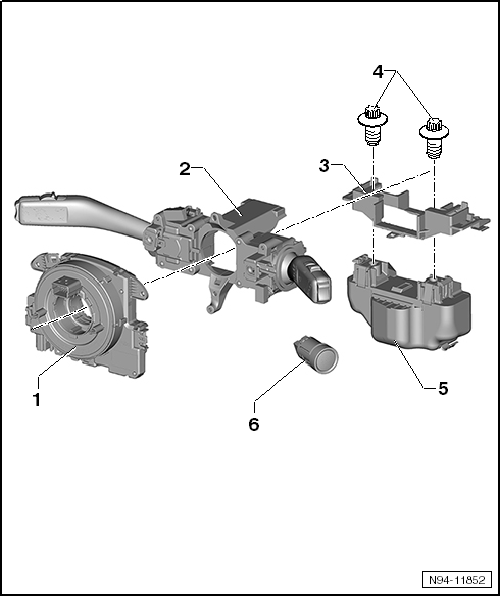
- Steering Column Electronics Control Module -J527
- Screw tightening specification: 1.5 Nm
- Follow the removing and installing sequence.
- Removing and Installing, Valeo.
- Removing and Installing, Kostal.
- Coding.
- Steering Column Combination Switch -E595-
- Follow the removing and installing sequence.
- Removing and Installing, Valeo.
- Removing and Installing, Kostal.
- Steering Column Switch Mount
- Follow the removing and installing sequence.
- Removing and installing, Valeo.
- Removing and installing, Kostal.
- Shear Bolts
- Break-off torque: approximately 15 Nm
- M8 x 20
- Electronic Steering Column Lock Control Module -J764-
The Electronic Steering Column Lock Control Module -J764- and the steering column switch mount are removed and installed together.
- Follow the removing and installing sequence.
- Removing and installing.
- Coding.
- Start System Button -E378-
- Removing and installing.
Steering Column Switch Components, Removal and Installation Sequence
Caution
Follow the procedure in the Repair Manual when disconnecting and connecting the battery.
WARNING
Before working on electronic system and removing the steering wheel the following conditions must be met:
The technician must discharge static electricity. This is accomplished by touching grounded metal like, for example, water pipes, heating pipes, metal carriers or a heater pipe.
If this note is ignored it can result in failure of the control modules during later operation.
- Remove the battery ground cable.
- Wheels must be located in straight ahead position.
If this note is ignored, it can result in failure of the airbag system during later operation.
Caution
If the universal joint is separated from the steering gear, or the Steering Angle Sensor -G85- is removed, do not perform the following tasks:
- Connecting the battery
- Turning on the ignition
- Turning the steering gear.
- Turning the steering column.
These points must be followed otherwise, it can lead to irreparable damage.
The shear bolts must be drilled out when removing the entire steering column switch including the mount and the Electronic Steering Column Lock Control Module -J764-. New shear bolts are required when installing the Electronic Steering Column Lock Control Module -J764-.
Also, if only one individual component of steering column switch is removed or replaced, the sequence described in the following must always be adhered to.
Removing
- Disconnect the battery.
WARNING
- Risk of airbag deployment.
- The airbag unit could deploy if mishandled.
- Follow the safety precautions when working on the airbag.
- Remove the steering wheel.
- Remove the steering column trim panel.
Remove the steering column switch components in the following sequence:
- Steering Column Electronics Control Module -J527-.
- Steering Column Combination Switch -E595-.
- Electronic Steering Column Lock Control Module -J764-.
- Steering column switch mount.
Installing
Install in reverse order of removal.

 Steering Column Electronics Control Module -J527-
General Information
The Steering Column Electronics Control Module -J527- includes the following
components and cannot be disassembled:
Airbag Spiral Spring/Return Spring with Slip Ring -F138-
Ste ...
See More:
Volkswagen Tiguan Service and Repair Manual > Interior Lights, Switches: Interior Lamps and Switches
Interior Monitoring Deactivation Switch -E267-
Interior Monitoring Deactivation Switch -E267-, Removing and Installing
The Interior Monitoring Deactivation Switch -E267- is installed inside the
B-pillar trim panel on the driver side.
Special tools and workshop equipment required
Trim Removal Wedg ...
Volkswagen Tiguan Owners Manual
Volkswagen Tiguan Service and Repair Manual
- Body exterior
- Body Interior
- General Paint Information
- Paint
- Brake System
- Suspension, Wheels, Steering
- Wheel and Tire Guide
- Towing Guide
- Wheel and Tire Guide General Information
- Communication
- Electrical Equipment General Information
- Electrical Equipment from 06/2011
- Heating, Ventilation and Air Conditioning
- Refrigerant R134a Servicing
- 6-Speed Manual Transmission 02Q, OBB, and OFB
