Volkswagen Tiguan Service and Repair Manual: "RNS 510" Radio/Navigation System
General Information
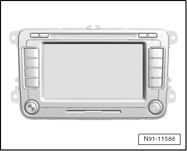
"RNS 510" Radio/Navigation System
The Radio Navigation System "RNS 510" combines the functions of a navigation system with those of a high-value RDS vehicle radio.
The following described the main functions:
- RDS radio receiver
- 6.5 inch multicolor display with touch screen
- Navigation system with GPS satellite receiver
- integrated antenna diversity
- integrated DAB tuner for digital radio reception
- DVD player for navigation, video and audio
- SD memory card slot
- A hard disc drive for storing data is installed inside the unit
- Corridor function
- Playback formats MP3 and WMA
The "RNS 510" radio navigation system has four speaker outputs.
The "RNS 510" can be expanded to include the following components:
- CD Changer
- Multifunction Steering Wheel
- TV Tuner
- Amplifier
- Universal cellular telephone preparation (UHV Premium light)
- Rear Seat Entertainment
The antenna is inside the rear side windows and the antenna system is integrated inside the radio "diversity function".
The navigation antenna is a roof antenna.
Refer to the Owner's Manual and → No.397 for additional information.
Use the Vehicle Diagnostic Testerin the "Guided Fault Finding" function and → Wiring diagrams, Troubleshooting & Component locations when servicing or fault finding.
Overview - "RNS 510" Radio Navigation System
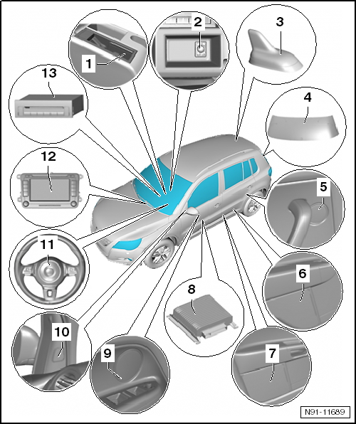
- External Multimedia Device Interface -R215-
- Located inside the center armrest storage compartment
- For more information regarding the External Multimedia Device Interface -R215-.
- Optional installation of "CD changer" or "external multimedia device interface-". The two systems cannot be installed together because the installation location is the same for both.
- External Audio Source Connection -R199-
- Located inside the center armrest storage compartment
- Removing and installing.
- Telephone/Navigation System/Parking Heater Antenna -R66-
- Located on the roof at the back of the vehicle
- Installed only if, in addition to the radio, a telephone or auxiliary heater is installed at the factory
- For more information regarding the different antenna systems.
- Rear Window Antenna 1 -R130-
- Right Rear Treble Speaker -R16- and Left Rear Treble Speaker -R14-
- Installed inside the left and right side trim panels in the passenger compartment
- For more information regarding the different speaker systems.
- Right Rear Bass Speaker -R17- and Left Rear Bass Speaker -R15-
- Installed inside the left and right side trim panels in the passenger compartment
- For more information regarding the different speaker systems.
- Right Front Bass Speaker -R23- and Left Front Bass Speaker -R21-
- Installed inside the left and right doors
- Midrange frequencies play through the bass and treble speakers.
- For more information regarding the different speaker systems.
- Amplifier -R12-
- Installed under the left front seat
- For more information regarding the amplifier.
- Right Front Midrange Speaker -R104- and Left Front Midrange Speaker
-R103-
- Installed in door trim of left and right front doors
- Only with higher quality sound systems or with the sound system amplifier
- For more information regarding the different speaker systems.
- Right Front Treble Speaker -R22- and Left Front Treble Speaker -R20-
- Installed inside the left and right doors
- For more information regarding the different speaker systems.
- Left Multifunction Buttons on Steering Wheel -E440- and Right
Multifunction Buttons on Steering Wheel -E441-
- For more information regarding the multifunction steering wheel.
- Radio/Navigation Display Unit Control Module -J503-
- Removing and installing.
- Connector overview.
- Anti-theft coding.
- CD Changer -R41-
- 6 disc CD changer
- Located inside the center armrest storage compartment
- For more information regarding the CD changer.
- Optional installation of "CD changer" or "external multimedia device interface". The two systems cannot be installed together because the installation location is the same for both.
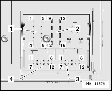
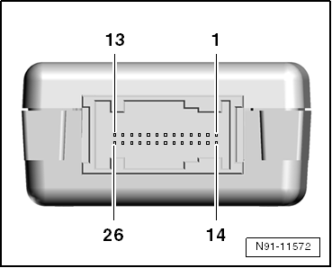
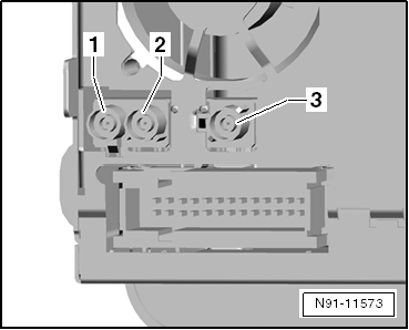
Overview - "RNS 510" Radio Navigation System Connector
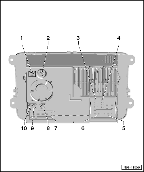
- Navigation Connection, Japan
- Not Assigned
- Antenna Connection
- Input connector for the DAB antenna, optional
- Multi-Pin Connector 1, 8-Pin
- Terminal assignment.
- Multi-Pin Connector 2, 8-Pin
- Terminal assignment.
- Multi-Pin Connector 3, 12-Pin
- Terminal assignment.
- Multi-Pin Connector 4, 12-Pin
- Terminal assignment.
- 26-pin Connector
- Terminal assignment.
- Antenna Connection
- For navigation
- For more information.
- Antenna Connection
- FM 2 Antenna
- For more information.
- Antenna Connection
- FM/AM antenna
- For more information.
8-pin Multi-Pin Connector 1, for Speaker Outputs
- Right Rear Speaker, Positive
- Right Front Speaker, Positive
- Left Front Speaker, Positive
- Left Rear Speaker, Positive
- Right Rear Speaker, Negative
- Right Front Speaker, Negative
- Left Front Speaker, Negative
- Left Rear Speaker, Negative
8-Pin Multi-Pin Connector 2, for the Power Supply and CAN-Bus
- CAN Bus High
- CAN Bus Low
- BOSE Pin
- Power Supply, Negative, Terminal 31
- Not Assigned
- Not Assigned
- Voltage Supply, Positive, Terminal 30
- Control Signal for the Anti-Theft Coding, SAFE, Positive

12-Pin Multi-Pin Connector 3, for Telephone and Microphone Signals
- Microphone Input, Negative
- Not Assigned
- Not Assigned
- Microphone Output, Negative
- Left Telephone Audio Input Signal, Negative
- Right Telephone Audio Input Signal, Negative
- Microphone Input, Positive
- Not Assigned
- Microphone Output, Positive
- Telephone Mute (Radio Mute)
- Left Telephone Audio Input Signal, Positive
- Right Telephone Audio Input Signal, Positive

12-Pin Multi-Pin Connector 4, for CD Changer Controls and the CD Audio Input Signals
- Left Input AUX Signals
- AUX Signal Ground
- CD Changer, Audio Signal Ground
- CD Changer, Voltage Supply, Positive, Terminal 30, Contact Continuous Power Handling Greater Than 1A, Short-Term Peak Power Handling 5A
- Not Assigned
- CD Changer, DATA OUT (Data Exchange for CD Changer Control from the Radio Navigation System to the CD Changer)
- Right Input AUX Signals
- CD Changer, Audio Left Channel, CD/LA
- CD Changer, Audio Right Channel, CD/R
- CD Changer, Control Wire, Switched Positive
- CD Changer, DATA IN (Data Exchange for the CD Changer Control from the CD Changer to the Radio Navigation System)
- CD Changer, CLOCK (Internal Test Protocol for Monitoring Data Flow)

26-Pin Multi-Pin Connector, Audio and Video
- Reserved For Protocol Debug RX
- Reserved For Protocol Debug TX
- Not Assigned
- Not Assigned
- Video Output LF, Right
- Video Signal Output, Shielding Ground
- Video Signal Output, Vertical and Horizontal Synchronization
- Video Signal Output, Green
- Not Assigned
- Right Video Signal Input LF
- Video Signal Input, Shielding Ground
- Video Signal Input, Vertical and Horizontal Synchronization
- Video Signal Input, Green
- Not Assigned
- Not Assigned
- Not Assigned
- Video Signal Input LF, Negative
- Video Signal Output, LF, Left
- Video Signal Output, RGBS, Negative
- Video Signal Output, Blue
- Video Signal Output, Red
- Video Signal Input LF, Negative
- Left Video Signal Input LF
- Video Signals Input, RGBS, Negative
- Video Signal Input, Blue
- Video Signal Input, Red
Antenna Connectors 8 through 10
- Terminal Connector Antenna Radio Reception AM and FM, Double Fakra, No Coding, Impedance 50 Ohm, Color Cream White
- Terminal Connector Antenna Radio Reception FM2, Double Fakra, Coding B, Impedance 50 Ohm, Color Cream White
- Terminal Connector Antenna Navigation, Fakra, Coding C, Impedance 50 Ohm, Color Signal Blue
Anti-Theft Code
General Information
Radio navigation system "RNS 510" is equipped with an electronic convenience anti-theft system which operates in conjunction with the instrument cluster.After disconnecting the power supply, the radio navigation system is ready to be used again once the power supply is connected. The anti-theft code does not need to be entered again. The anti-theft coding must be activated for the first time and the radio navigation system must be connected in the same vehicle.
Reactivating a locked radio/navigation system is only possible by entering correct radio code number for anti-theft protection.Use the Vehicle Diagnostic Tester to get the anti-theft code. The radio card and the label on the radio that were used in the past are no longer used.
Note
The Vehicle Diagnostic Tester must be "online" (connected to the network) in order to get the anti-theft code and the user must be authorized to access radio codes.
Anti-Theft Code, Deactivating
Special tools and workshop equipment required
- Vehicle Diagnostic Tester
- Vehicle Diagnosis System - Updated Cable - 3m -VAS5051/5a- or Vehicle Diagnosis System - Diagnostic Cable - VAS5051/6a- or Vehicle Diagnostic Tester - Diagnostic Cable - 5m -VAS5052/3-
Select "Guided Functions" or "Guided Fault Finding".
After all control modules have been checked:- Press the "GO TO" button.
- Select "Functions/Component selection".
- Select "Body".
- Select "Electrical Equipment".
- Select "01-OBD-capable system".
- Select "Radio navigation system".
- Select "Functions"
- Select and start "radio code inquiry".
Authorization will be requested from the system: Then the operating data, the VIN and the radio serial number of the radio and radio/navigation system will be automatically read out.
Note
When installing new radio / radio-navigation unit, or a unit which has not be adapted to the vehicle, it can happen that tester will not be able to read the serial number of the radio / radio-navigation unit. In this case, enter the serial number manually. The serial number can be found on a sticker on the unit and is also stamped into the side of the unit.Then the anti-theft code will be displayed in the tester.
The radio navigation system anti-theft code must not be entered manually.Deactivating the Anti-Theft Coding
- Enter the anti-theft code appearing in the display in the "RNS 510" number block and confirm it.
Unit is enabled and ready for operation.
Note
If the anti-theft code has been entered incorrectly, it can be corrected immediately in another attempt. If anti-theft code is entered incorrectly twice, then the radio navigation system is locked for an hour. Leave radio navigation system and ignition switched on. The remaining running time appears in the radio navigation system display. After one hour, then the procedure for deactivating the anti-theft system can be repeated. Remember that you always have two attempts to enter the code. After that, the radio navigation system will be locked up for one hour.
 "RNS 315" Radio/Navigation System
General Information
"RNS 315" Radio/Navigation System
Note
Familiarity with the function and operation of the digital sound system
is needed if there are customer concerns.
Refer to the Owner's M ...
 Sound System Amplifier
General Information
Note
Before troubleshooting or servicing, the technicians must be familiar
with the function and operation of the radio and radio navigation system.
Refer to the Owner's Manua ...
See More:
Volkswagen Tiguan Service and Repair Manual > Seat Frames: Passenger Seat with Pass-Through
Sill-Side Trim Panel, Removing and Installing
Removing
Remove the cover -1- and remove the release
lever -2-.
Pull the height adjustment handle -1-
upward.
Using a small screwdriver, push the metal tab on the clamp
-2- located on the inside of the height
adjustment handle, toward the s ...
Volkswagen Tiguan Owners Manual
Volkswagen Tiguan Service and Repair Manual
- Body exterior
- Body Interior
- General Paint Information
- Paint
- Brake System
- Suspension, Wheels, Steering
- Wheel and Tire Guide
- Towing Guide
- Wheel and Tire Guide General Information
- Communication
- Electrical Equipment General Information
- Electrical Equipment from 06/2011
- Heating, Ventilation and Air Conditioning
- Refrigerant R134a Servicing
- 6-Speed Manual Transmission 02Q, OBB, and OFB
