Volkswagen Tiguan Service and Repair Manual: RCD 510 Radio System
General Information
View of the "RCD 510" Radio
Note
- Familiarity with the function and operation of the digital sound system is needed if there are customer concerns.
- Refer to the Owner's Manual
- Anti-theft code is equipped with protection code number.
- For servicing or trouble shooting, use the Vehicle Diagnostic Tester in "Guided Fault Finding".
- When the battery is reconnected, check any affected system or component (radio, clock, comfort electrical connection etc.) according to the repair manual and/or the Owner's Manual.
- The CD changer in the "RCD 510" has a transport protection that must be deactivated when a new unit is installed. The transport protection must also be activated before shipping in units that have been removed from the vehicle. To do this, the "RCD 510" must still be connected to the voltage supply. CD changer transport protection in "RCD 510", activating and deactivating.
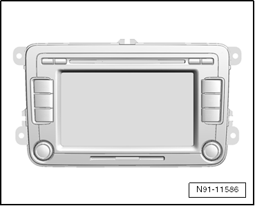
The RCD 510 radio has the following features:
- 6.5 inch multicolor display with touch screen
- 4 speaker channels with 20 watts each
- Integrated 6 disc CD changer
- Connector position for using SD memory cards for audio playback
- Control for an external 6-CD changer
- Telephone control (hands free)
- Externally connectable sound amplifier
- iPod connection (USB), optional
The "RCD 410" radio consists of the radio and the front and rear speakers.
The CD player integrated inside the radio plays the following CD formats:
- CD-R
- CD-RW
- MP3
- wma
Note
- Mix CDs (CDs that contain computer data and also music) cannot be played.
- The antenna is integrated inside the radio unit with "diversity function".
Overview - "RCD 510" Radio System
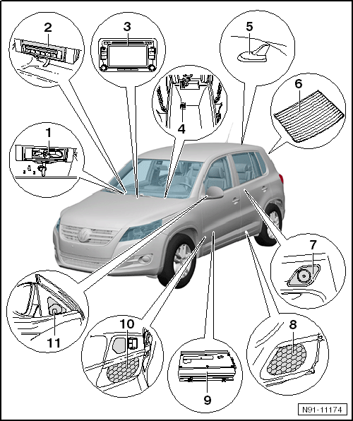
- External Multimedia Device Interface -R215-
- Installed in the center console
- Additional information can be found in external multimedia device interface chapter.
- Optional "CD changer" or "external multimedia device interface". It is not possible to have both systems together because both systems have the same installation location.
- CD Changer -R41-
- 6 disc CD changer
- Installed in the center console
- For more information regarding the CD changer.
- Optional "CD changer" or "external multimedia device interface". It is not possible to have both systems together because both systems have the same installation location.
- Radio -R-
- Removing and installing.
- Connector overview.
- Transport protection device of CD changer in "RCD 510", activating/deactivating.
- Anti-theft coding.
- External Audio Source Connection -R199-
- Located inside the storage compartment under the center armrest
- For more information regarding the External Audio Source Connection -R199-.
- Telephone/Navigation System/Parking Heater Antenna -R66-
- Located on the roof at the back of the vehicle
- For more information regarding the different antenna systems.
- Window Antennas
- Installed in the rear window, for radio reception with antenna diversity
- Antenna for digital radio reception, DAB, also optional
- For more information regarding the different antenna systems.
- Right Rear Treble Speaker -R16- and Left Rear Treble Speaker -R14-
- Installed in door trim of left and right rear doors
- For more information regarding the different speaker systems.
- Right Rear Bass Speaker -R17- and Left Rear Bass Speaker -R15-
- Installed in door trim of left and right rear doors
- For more information regarding the different speaker systems.
- Amplifier -R12-
- Installed under the left front seat
- For more information regarding the amplifier.
- Right Front Midrange Speaker -R104- and Left Front Midrange Speaker
-R103- as well as Right Front Bass Speaker -R23- and Left Front Bass Speaker
-R21-
- Installed in door trim of left and right front doors
- Midrange speakers are only installed in conjunction with sound system
- The midrange speaker and the bass speaker are a single unit.
- Only the bass speaker is installed here when there is no sound system. Midrange frequencies play through the bass and treble speakers.
- For more information regarding the different speaker systems
- Right Front Treble Speaker -R22- and Left Front Treble Speaker -R20-
- Installed in triangle window of left and right front doors
- For more information regarding the different speaker systems.
Cd Changer Transport Protection in "RCD 510", Activating and Deactivating
The transport protection on a "RCD 510" must be activated before shipping and deactivated when installing a new unit. This takes place electronically over the unit's buttons. After activating the transport protection, the CD changer mechanism is brought into "transport position".
Transportation Safeguard, Activating
Status: "ON", the wiring connections must be connected to the "RCD 510".
- Press and hold buttons marked with -arrows- simultaneously for 5 seconds.

Now the transport protection is activated.
Transportation Safeguard, DeactivatingStatus: "ON", the wiring connections must be connected to the "RCD 510".
- Press and hold buttons marked with -arrows- simultaneously for 5 seconds.
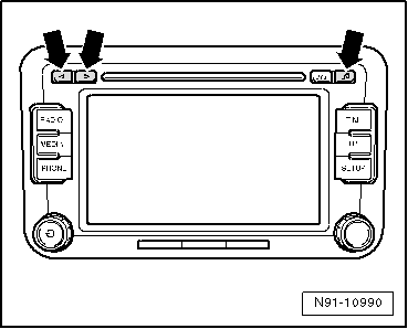
CDC transport protection activated appears in the radio display.
Underneath the "deactivating" button also appears.
- Press the "deactivating" button.
Now the transport protection is deactivated.
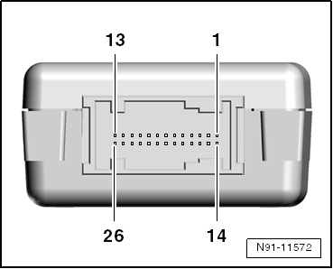
Overview - "RCD 510" Radio, Connector
Multi-Pin Connector 1, 8-Pin, Speaker Outputs
- Right Rear Speaker, Positive
- Right Front Speaker, Positive
- Left Front Speaker, Positive
- Left Rear Speaker, Positive
- Right Rear Speaker, Negative
- Right Front Speaker, Negative
- Left Front Speaker, Negative
- Left Rear Speaker, Negative

8-Pin Connector 2, Voltage Supply, CAN-Bus, Telephone Muting
- CAN Bus High
- CAN Bus Low
- Supply Voltage Supply, Connected, Positive
- Negative Connection, Terminal 31
- CAN Bus Display, Negative
- CAN Bus Display, Positive
- Positive Connection, Terminal 30
- Control Signal For The Anti-Theft Coding, SAFE
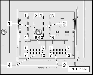
12-Pin Connector 3, AUX Audio Output, Telephone Signal Input
- Microphone Input, Negative
- AUX Output, Audio, Positive, Right
- AUX Output, Audio, Negative
- Microphone Output, Negative
- Telephone LF Signal Input, Left, Negative
- Telephone LF Signal Input, Right, Negative
- Microphone Input, Positive
- AUX Output, Audio, Positive, Left
- Microphone Output, Positive
- Telephone Mute
- Telephone LF Signal Input, Left, Positive
- Telephone LF Signal Input, Right, Positive

26-Pin Connector 5, Audio and Video
- Reserved for Protocol Debug RX
- Reserved for Protocol Debug TX
- Not Assigned
- Not Assigned
- Video Output LF, Right
- Video Signal Output, Shielding Ground
- Video Signal Output, Vertical And Horizontal Synchronization
- Video Signal Output, Green
- Not Assigned
- Right Video Signal Input LF
- Video Signal Input, Shielding Ground
- Video Signal Input, Vertical And Horizontal Synchronization
- Video Signal Input, Green
- Not Assigned
- Not Assigned
- Not Assigned
- Video Signal Input LF, Negative
- Video Signal Output, LF, Left
- Video Signal Output, RGBS, Negative
- Video Signal Output, Blue
- Video Signal Output, Red
- Video Signal Input LF, Negative
- Left Video Signal Input LF
- Video Signals Input, RGBS, Negative
- Video Signal Input, Blue
- Video Signal Input, Red
Anti-Theft Code
General Information
The radio is equipped with convenience anti-theft protection, which operates in conjunction with the instrument cluster.
After disconnecting the power supply, the radio can be used again after connecting the power supply. The anti-theft code does not need to be entered again. The requirement is that the anti-theft coding must be activated for the first time and that the radio is reconnected in the same vehicle.
Use the Vehicle Diagnostic Tester to get the anti-theft code. The radio card and the label on the radio that were used in the past are no longer used.
Note
The Vehicle Diagnostic Tester must be "online" (connected to the network) in order to get the anti-theft code and the user must be authorized to access radio codes.
Anti-Theft Coding, Deactivating
Required Special Tools and Equipment
- Vehicle Diagnostic Tester
- Vehicle Diagnosis System - Updated Cable - 3m - VAS5051/5a- or Vehicle Diagnosis System - Diagnostic Cable -VAS5051/6a- or Vehicle Diagnostic Tester - Diagnostic Cable - 5m -VAS5052/3-
Retrieving the Anti-Theft System Code Using the VAS Tester
Select "Guided Functions" or "Guided Fault Finding" on the Vehicle Diagnostic Tester.
After all control modules have been checked:
- Press the "GO TO" button.
- Select "Functions/Component selection".
- Select "Body".
- Select "Electrical Equipment".
- Select "01-OBD-capable system".
- Select "radio or radio navigation system".
- Select "Functions"
- Select and start "radio code inquiry".
Authorization will be requested from the system: Then the operating data, the VIN and the radio serial number of the radio/navigation system will be automatically read out.
Note
When installing new radio / radio-navigation unit, or a unit which has not be adapted to the vehicle, it can happen that tester will not be able to read the serial number of the radio / radio-navigation unit. In this case, enter the serial number manually. The serial number can be found on a sticker on the unit and is also stamped into the side of the unit.
Then the radio code will be displayed in the tester.
The radio or radio navigation system anti-theft code must now be entered manually.
Deactivating the Anti-Theft Coding
- Switch on radio.
An input mask with a 10-key keypad and a correction surface and an input surface appears.
- Enter the correct radio code using the key pad on the input mask.
- Confirm by pressing the input button.
Unit is enabled and ready for operation.
Using the correction button to change an incorrect number.
Note
If the wrong code number was entered when overriding the electronic lock, first "SAFE" blinks in the display and "1000" appears again. The entire procedure can now be repeated one more time. The number of tries is shown in the display. If you enter the wrong code again, the unit is locked for about one hour, meaning it cannot be operated. This lock is indicated by the word "SAFE" appearing continuously in the display. After one hour has passed in which the unit and the ignition must be switched on, the number of attempts disappears and the electronic lock can be deactivated again as described above. The cycle "two attempts, locked for one hour" still applies.
 "RCD 500" Radio System
General Information"RCD 500"
Radio
Note
Familiarity with the function and operation of the digital sound system
is needed if there are customer concerns.
Refer to the Owner's Manual for addition ...
 "Premium 7" Radio System
General Information
Premium 7 Radio
Note
Familiarity with the function and operation is needed if there are
customer concerns. Refer to the Owner's Manual.
Anti-theft coding is equipped with prot ...
See More:
Volkswagen Tiguan Service and Repair Manual > Tire Information: Run-Flat Tire PAX
Tires, Storing
Storage Room
Tire storage must be:
Dark,
Dry,
Cool and
Ventilated
WARNINGStored tires must not come in contact with fuel, oil, grease or
chemicals under any circumstances. Otherwise, the material in the tire will be
damaged by chemical reactions which are not always visible.Th ...
Volkswagen Tiguan Owners Manual
Volkswagen Tiguan Service and Repair Manual
- Body exterior
- Body Interior
- General Paint Information
- Paint
- Brake System
- Suspension, Wheels, Steering
- Wheel and Tire Guide
- Towing Guide
- Wheel and Tire Guide General Information
- Communication
- Electrical Equipment General Information
- Electrical Equipment from 06/2011
- Heating, Ventilation and Air Conditioning
- Refrigerant R134a Servicing
- 6-Speed Manual Transmission 02Q, OBB, and OFB
