Volkswagen Tiguan Service and Repair Manual: "RCD 210" Radio System
General Information
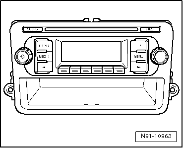
"RCD 210" Radio View
Note
- Familiarity with the function and operation of the digital sound system is needed if there are customer concerns.
- Additional information. Refer to operating instructions.
- Anti-theft coding is equipped with a protection code number.
- Servicing or trouble shooting, use the Vehicle Diagnostic Tester"Guided Fault Finding".
- When the battery is reconnected, check any affected system or component (radio, clock, comfort electrical connection etc.) according to the repair manual and/or the Owner's Manual.
The radio is equipped with a 2x20 watt end stage output performance.
The radio is also available with a 4x20 watt end stage output performance. In this case, there are speakers in the rear.The speakers are designed as a 2-way system.
Each front door has a bass speaker and a treble speaker.As an option, each rear door has a bass speaker and a treble speaker.
There is also the possibility to connect a CD changer. If telephones are being used, there is telephone muting and signal input for telephone LF signal available.
The CD drive, which is integrated inside the radio, can play the following CD formats:
- CD-R
- CD-RW
- MP3
Note
- Music CDs with 8 cm diameter (mini-discs) cannot be played back.
- Mix CDs (CDs that contain computer data and also music) cannot be played.
The antenna is inside the rear window and does not have "diversity function".
Overview - "RCD 210" Radio System
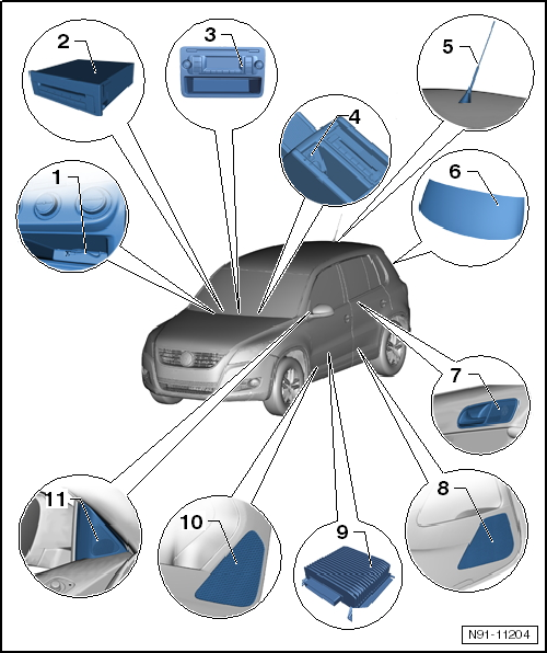
- External Multimedia Device Interface -R215-
- Installed in the center console
- Additional information can be found in the external multimedia device interface chapter.
- Optional installation of "CD Changer" or "External Multimedia Device Interface". Both systems are not available together because they both use the same installation location.
- CD Changer -R41-
- 6 disc CD changer
- Located inside the glove compartment
- For more information regarding the CD changer.
- Optional installation of "CD Changer" or "External Multimedia Device Interface". Both systems are not available together because they both use the same installation location.
- Radio -R-
- Removing and installing.
- Connector overview.
- Anti-theft coding.
- External Audio Source Connection -R199-
- Located inside the storage compartment under the center armrest
- Removing and installing.
- Telephone/Navigation System/Parking Heater Antenna -R66-
- Located on the roof at the back of the vehicle
- For more information regarding the different antenna systems.
- Window Antennas
- Installed in the rear window, for radio reception with antenna diversity
- Antenna for digital radio reception, DAB, also optional
- For more information regarding the different antenna systems.
- Right Rear Treble Speaker -R16- and Left Rear Treble Speaker -R14-
- Installed in door trim of left and right rear doors
- For more information regarding the different speaker systems.
- Right Rear Bass Speaker -R17- and Left Rear Bass Speaker -R15-
- Installed in door trim of left and right rear doors
- For more information regarding the different speaker systems.
- Amplifier -R12-
- Installed under the left front seat
- For more information regarding the sound system amplifier.
- Right Front Midrange Speaker - R104- and Left Front Midrange Speaker
-R103- as well as Right Front Bass Speaker -R23- and Left Front Bass Speaker
-R21-
- Installed in door trim of left and right front doors
- Midrange speakers are only installed in conjunction with sound system
- The midrange speaker and the bass speaker are a single unit.
- Only the bass speaker is installed here when there is no sound system. Midrange frequencies play through the bass and treble speakers.
- For more information regarding the different speaker systems.
- Right Front Treble Speaker -R22- and Left Front Treble Speaker -R20-
- Installed in triangle window of left and right front doors
- For more information regarding the different speaker systems.
Overview - "RCD 210" Radio, Connector
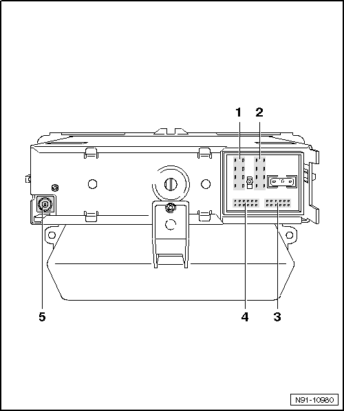
- Multi-Pin Connector 1, 8-Pin, Speaker Outputs
- Terminal assignment.
- Multi-Pin Connector 2, 8-Pin, Voltage Supply, CAN Bus
- Terminal assignment.
- 12-Pin Connector 3, Telephone Signal Input, Telephone Mute
- Terminal assignment.
- 12-Pin Connector 4, AUX Audio Input, CD Changer Control and CD Audio
Input Signals
- Terminal assignment.
- Connector 5, Antenna Connection
- Beige connector color
- Connection for the antenna wire to the antenna
Anti-Theft Code
General Information
The radio is equipped with convenience anti-theft protection, which operates in conjunction with the instrument cluster.After disconnecting the radio power supply, the radio is ready for use again once the power supply is connected. The anti-theft code does not need to be entered again. The requirement is that the electronic anti-theft system must be activated for the first time and that the radio is reconnected in the same vehicle.
Anti-Theft Coding, Deactivating
The anti-theft code is transmitted via the Vehicle Diagnostic Tester. The radio card and the label on the radio that were used in the past are no longer used.
Note
To access the anti-theft code, the Vehicle Diagnostic Tester must be connected "online" (network connection) and the user must provide a valid user rights to retrieve a radio code.
Required Special Tools and Equipment
- Vehicle Diagnostic Tester
Retrieving the Anti-Theft Code for the Electronic Anti-Theft System Using the VAS Tester
Select "Guided Functions" or "Guided Fault Finding" on the Vehicle Diagnostic Tester.
After all control modules have been checked:
- Press button "Jump".
- Select "Function/Component Selection".
- Select "Body".
- Select "Electrical Equipment".
- Select "01 OBD-capable systems".
- Select "radio or radio navigation system"
- Select "Functions"
- Select and start "radio code inquiry".
Authorization will be requested from the system: Then the operating data, the VIN and the Radio/Radio Navigation System unit serial number will be automatically read out.
Note
When installing new radio / radio-navigation unit, or a unit which has not be adapted to the vehicle, it can happen that tester will not be able to read the serial number of the radio / radio-navigation unit. In this case, enter the serial number manually. The serial number can be found on a sticker on the unit and is also stamped into the side of the unit.
Then the anti-theft code will be displayed in the tester.
The radio or radio navigation system anti-theft code must now be entered manually.
Deactivating the Electronic Anti-Theft Protection
- Switch on radio.
The unit automatically displays "SAFE" for 10 seconds. After that "1000" will appear and will stay on. No operating of buttons is required for this.
Position for code number to be set is indicated in display above the multi-function buttons with "_X_".
- Enter the code in the proper sequence using the four multifunction buttons. Press respective buttons in succession until the correct characters are shown in center of display.
- Then press the "OK" button. Unit is ready for operation again and switches to last operating state.
Note
If the wrong code number was entered when overriding the electronic lock, first "SAFE" blinks in the display and "1000" appears again. The entire procedure can now be repeated one more time. The number of tries is shown in the display. If you enter the wrong code again, the unit is locked for about one hour, that is, it cannot be operated. This lock is indicated by the word "SAFE" appearing continuously in the display. After one hour has elapsed in which the unit and the ignition must be switched on, the number of attempts disappears and the electronic lock can be deactivated again as described above. The cycle "two attempts, locked for one hour" still applies.
 Radio and Radio Navigation Systems, General Information
Radios and Radio Navigation Systems, Removing and Installing
Note
Use the chapter for the individual unit when removing and installing.
Removing
Do the following before starting the procedure:
Remov ...
 RCD 300" Radio System
General Information
RCD 300 Radio
Note
The part number for the radio is on a label on the radio housing.
If radio unit is replaced, always activate anti-theft coding. Refer to
the Owner's Manual. ...
See More:
Volkswagen Tiguan Service and Repair Manual > Subframe, Stabilizer Bar and Control Arms: Overview - Subframe, Stabilizer Bar and Control Arms
Note
Welding and straightening work on supporting or wheel carrying
components of suspension is not permitted.
Always replace self-locking nuts.
Always replace corroded bolts/nuts.
Bonded rubber bushings have a limited range of motion. Therefore tighten
threaded connections at components wi ...
Volkswagen Tiguan Owners Manual
Volkswagen Tiguan Service and Repair Manual
- Body exterior
- Body Interior
- General Paint Information
- Paint
- Brake System
- Suspension, Wheels, Steering
- Wheel and Tire Guide
- Towing Guide
- Wheel and Tire Guide General Information
- Communication
- Electrical Equipment General Information
- Electrical Equipment from 06/2011
- Heating, Ventilation and Air Conditioning
- Refrigerant R134a Servicing
- 6-Speed Manual Transmission 02Q, OBB, and OFB
