Volkswagen Tiguan Service and Repair Manual: Overview - Subframe, Stabilizer Bar and Control Arms
Volkswagen Tiguan Service and Repair Manual / Suspension, Wheels, Steering / Front Suspension / Subframe, Stabilizer Bar and Control Arms / Overview - Subframe, Stabilizer Bar and Control Arms
Note
- Welding and straightening work on supporting or wheel carrying components of suspension is not permitted.
- Always replace self-locking nuts.
- Always replace corroded bolts/nuts.
- Bonded rubber bushings have a limited range of motion. Therefore tighten threaded connections at components with bonded rubber bushings only when wheel bearing housing has been lifted (curb weight position).
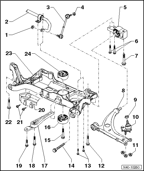
- Nut
- 65 Nm
- Always replace if removed
- Counterhold at socket head of joint bolt when tightening
- Self-locking
- Stabilizer Bar
- There are different versions.
- Allocation. Refer to the Parts Catalog.
- Removing and installing.
- Coupling Rod
- Stabilizer bar connection to the suspension strut
- Nut
- 65 Nm
- Always replace if removed
- Counterhold at socket head of joint bolt when tightening
- Self-locking
- Mounting Bracket
- Secure.
- With bonded rubber bushing
- Bolt
- 50 Nm + 90º
- Always replace if removed
- M10 x 70
- Bolt
- 70 Nm + 180º
- Always replace if removed
- M12 x 1.5 x 100
- Control Arm
- Replace with the ball joint if damaged.
- Removing and installing.
- Bearing, replacing.
- There may be different versions of the control arms (aluminum, sheet steel)
- Allocation. Refer to the Parts Catalog.
Note
Do not install control arms made of different materials on the right and left sides.
- Nut
- 60 Nm
- Always replace if removed
- M12 x 1.5
- Self-locking
- Ball Joint
- Checking.
- Removing and installing.
- Replace with the control arm if damaged.
- Nut
- With an aluminum control arm: 60 Nm
- With a steel control arm: 100 Nm
- Always replace if removed
- Self-locking
- Tighten only in curb weight position.
- Bolt
- M12 x 1.5 x 100: 70 Nm + 180º
- M12 x 1.5 x 110: 70 Nm + 90º additional turn
- Always replace if removed
- Bolt
- M8 x 55
- 20 Nm + 90º
- Always replace if removed
- Bolt
- 70 Nm + 180º additional turn
- Always replace if removed
- M12 x 1.5 x 110
- Tighten only in curb weight position.
- Bolt
- 100 Nm + 90º
- Always replace if removed
- M14 x 1.5 x 70
- Only tighten when pendulum support is bolted to transmission
- Lower Bonded Rubber Bushing for Pendulum Support
- Removing and installing.
- There are different versions.
- Allocation. Refer to the Parts Catalog.
- Pendulum Support
- Bolt first to the transmission, then to subframe
- There are different versions.
- Allocation. Refer to the Parts Catalog.
- Bolt
- M10 x 75: 50 Nm + 90º
- M12 x 1.5 x 85: 60 Nm + 90º
- Always replace if removed
- Bolt
- M10 x 35: 50 Nm + 90º
- M12 x 1.5 x 50: 60 Nm + 90
- Always replace if removed
- Heat Shield
- For FWD vehicles only
- Bolt
- 6 Nm
- Bolt
- 70 Nm + 180º
- Always replace if removed
- M12 x 1.5 x 90
- Subframe
- Removing and installing without the steering gear.
- Removing and installing with steering gear.
- There are different versions.
- Allocation. Refer to the Parts Catalog.
- Upper Bonded Rubber Bushing for Pendulum Support
- Removing and installing.
- There are different versions.
- Allocation. Refer to the Parts Catalog.
Identifying the Pendulum Support Bonded Rubber Bushing
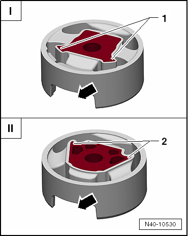
Note
- There are two different versions of the pendulum support bonded rubber bushing: the T version -I- and the V version -II-.
- Refer to the Parts Catalog for the allocation.
- The corners on the inner core -1- face toward the opening for the pendulum support -arrow- (T version).
- The corners on the inner core -2- face away from the opening for the pendulum support -arrow- (V version).
Longitudinal Member Threads, Servicing
Servicing the weld nut threads in the longitudinal member is possible under certain conditions.

 Subframe, Securing
Special tools and workshop equipment required
Locating Pins -T10096-
Engine and Gearbox Jack -VAS6931-
Locating Pins -T10096-, Installing
To secure the subframe, the Locating Pins -T10096- must be ...
See More:
Volkswagen Tiguan Owners Manual > Airbag system: Airbags and how they work
Read and follow the introductory information and
safety information first⇒Introduction
to the subject Front airbags and how they work
Airbags are only supplemental restraints. They are not a substitute for safety
belts that must be worn even though the front seating positions are equipped ...
Volkswagen Tiguan Owners Manual
Volkswagen Tiguan Service and Repair Manual
- Body exterior
- Body Interior
- General Paint Information
- Paint
- Brake System
- Suspension, Wheels, Steering
- Wheel and Tire Guide
- Towing Guide
- Wheel and Tire Guide General Information
- Communication
- Electrical Equipment General Information
- Electrical Equipment from 06/2011
- Heating, Ventilation and Air Conditioning
- Refrigerant R134a Servicing
- 6-Speed Manual Transmission 02Q, OBB, and OFB

© 2018-2026 Copyright www.vwtiguan.org - 0.0776