Volkswagen Tiguan Service and Repair Manual: General, Technical data
Safety Precautions
Safety Precautions when Working on Air Conditioning Systems Safety Precautions
WARNING
There is a risk of getting frostbite from the refrigerant.Refrigerant can come out under pressure when working on the A/C system. Frostbite on the skin and other parts of the body is possible.
Wear safety gloves.Wear protective eyewear.
Extract refrigerant and open the refrigerant circuit immediately.If more than 10 minutes elapse after extracting the refrigerant and the refrigerant circuit was not opened, extract the refrigerant again. Pressure develops in the refrigerant circuit due to evaporation.
Caution
Risk of Destroying the Refrigerant Lines.
The refrigerant lines can be destroyed by ripping through the inner foil.
Never bend the refrigerant lines to a radius smaller than r = 100 mm.
Safety Precautions when Working on Start/Stop System
WARNING
There is a risk of injury from the engine starting unexpectedly.The engine can start unexpectedly on vehicles with an activated Start/Stop System. A message appears in the instrument cluster indicating whether the Start/Stop System is activated.
Deactivate the Start/Stop System: Turn off the ignition.Safety Precautions when Working on Cooling System
WARNING
There is a risk of scalding from hot coolant.The cooling system is under pressure when the engine is warm. There is a risk of scalding from hot steam and coolant.
Wear safety gloves.Wear protective eyewear.
Reduce the pressure: cover the coolant reservoir cap with a cloth and carefully open.General Information
Odors in Vehicles with A/C System
- If there are unpleasant odors coming from the evaporator, clean the evaporator.
- For cleaning the evaporator, Volkswagen has tested and approved the Ultrasound A/C Cleaner -VAS6189B- as well as the Suction Feed Spray Gun -VAG1538- with a suitable spray nozzle.
- Instructions for cleaning the evaporator are provided with the tools.
- As soon as Volkswagen approves new procedures, the relevant notes can be found in the repair manual.
Vehicles with Start/Stop System General Information
The following Termination Conditions Deactivate the Start/Stop Function:
- The start/stop system was switched off by the start/stop mode button.
- The Battery -A- charge level does not allow the engine to start again (start voltage prediction).
- The defrost function is active.
- The windshield defogger is active.
- The set temperature on the display control head differs more than 8 ºC (46.4 ºF) from the actual interior temperature.
- The engine speed is greater than 1200 RPM.
- The Generator -C- is faulty, for example if the ribbed belt is torn.
- The coolant temperature is not in the specified range of 25 ºC to 100 ºC (77º and 212 ºF).
- The blower speed was raised more than 4 levels.
Repair Information
Working on the Refrigerant Circuit
In some countries, other qualifications are required when opening the refrigerant circuit.
Further Information
- Information regarding repair work on vehicles with A/C and handling refrigerant.
- Information regarding testing equipment and tools for repairs done on vehicles with A/C.
- Information regarding work using the A/C Service Station on vehicles with A/C.
- Conditions and procedures for flushing with refrigerant R134a.
Refrigerant Circuit Seals
- Replace the seals after removing.
- Coat the seals with refrigerant oil before installing.
- Make sure the seals are positioned properly on the pipe or in the groove.
- Ensure cleanliness when working. Even the smallest contaminant, a hair for example, can cause a leak.
- Only install seals that are resistant to refrigerant R134a and the corresponding refrigerant oil. These seals are color-coded to eliminate the risk of interchanging. Refer to Parts Catalog.
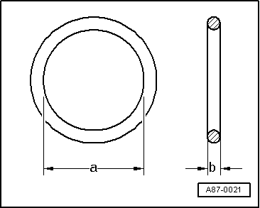
The dimensions -a and b- are dependent on the component location of the seal. Refer to Parts Catalog.
Actuator Information
Note
- Incorrectly installed actuators or connecting elements cause malfunctions in the heating or A/C system.
- Label the connectors to the actuators.
- Install the correct connecting elements on the actuators.
- Different actuators are installed on the air distribution box and the air intake unit for the heater and A/C unit. These actuators vary in their electrical values (due to their adjusting range, specified by the different connecting elements), connecting elements and in part number. Refer to the Parts Catalog. Therefore mark the actuators before removing it (risk of interchanging).
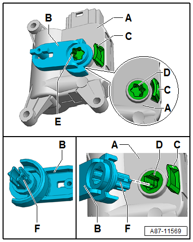
- The actuators gradually change starting from 11/04/2013. The connecting elements (levers, gears, etc., which are attached to the various actuators) to the doors in the heater and A/C unit varied by color up to this point in time. From 11/04/2013 actuators are installed with all connecting elements to the various doors for the heater and A/C unit being only one color (currently black). A color-coded allocation is therefore no longer possible. This illustration shows, for example, a Temperature Control Door Motor -V68--A- with the related connecting element (lever) -B-.
- Through 11/04/2013, various actuators were sent as a replacement part with a preinstalled color-coded connecting element (for example, the lever -B- to a Temperature Control Door Motor -V68--A-) with different part numbers. As a running change from 11/04/2013, an actuator is sent as a replacement part without the connecting element preinstalled and a set of connecting elements (for example, the lever -B- for a Temperature Control Door Motor -V68--A-). Refer to the Parts Catalog. Select the corresponding connecting element required from this set (depending on the version of the heater and A/C unit and on the actuator component location) and install it in the actuator shaft.

- Different actuator versions without the attached connecting elements -B- were installed or delivered as a replacement part from 11/04/2013. The actuator version, which is installed as a Recirculation Door Motor -V113- on a heater or a manual climate control system has , for example, no potentiometer (has stop switches for it). There are different adjustment ranges for actuators with potentiometer (electrically valuable adjustment range maximum approximately 120º or 340º). Refer to the Parts Catalog. Ensure the correct version and allocation. If an actuator with an incorrect adjustment range is installed, it will lead to problems, for example when performing the A/C system basic setting and/or when operating the heating and A/C system using the Vehicle Diagnostic Tester.
- After installing the actuator, perform the A/C system basic setting using the Vehicle Diagnostic Tester.
- Using the "output diagnostic test mode" and "basic setting" functions, the activation of the electrical components for the A/C system can be checked (for example, to check for interchanging). Use the Vehicle Diagnostic Tester in the "Guided Fault Finding" function.
- Check the activation and function of the adjustment motor using the display control head.
Connecting Element, Inserting in Actuator Shaft
Note
- Through 11/04/2013, various actuators were sent as a replacement part with a preinstalled color-coded connecting element (for example, the lever -B- to a Temperature Control Door Motor -V68--A-) and with different part numbers. As a running change from 11/04/2013, an actuator is sent as a replacement part without the connecting element preinstalled and with a set of connecting elements (for example, the lever -B- for a Temperature Control Door Motor -V68--A-). Refer to the Parts Catalog . If necessary, select the corresponding connecting element required from the set and insert it correctly allocated into the new actuator.
- The connecting element (for example, the lever -B-) can only be installed and engaged in the shaft -D- of the actuator -A- in one position.
- The connecting elements installed in the actuators that were installed through 11/04/2013 (for example, lever -B-) are locked in the shaft -D- of the actuator. They can be pried out using, for example, two screwdrivers.
- So that the respective connecting element -B- can be inserted into the shaft -D- of the actuator, it must be located in the position illustrated.
Connecting Element, Inserting
- Remove the connecting element from the removed actuator (by carefully prying it out using, for example, two screwdrivers) or select the required connecting element from the set of connecting elements. Refer to Parts Catalog .
Note
- If the wrong connecting element is selected or mounted, it may be possible to install the actuator. Problems may occur however when adapting the newly installed actuator.
- The connecting elements are to some extent very similar, therefore make sure it is the correct version.
- Only insert a connecting element that exactly matches the form of the removed connecting element.
- The connecting element can be installed with the actuator despite being incorrectly assigned. Problems may occur however when adapting the newly installed actuator.
- The various actuators are identical in construction and only differ in their part number. Therefore make sure it is the correct version.
- Only install actuators that can be explicitly allocated.
Note
- The connecting elements available in the set are not color-coded. Refer to the Parts Catalog .
- The possible adjusting range of an actuator is determined by the shape of the connecting element -B- and the stop -C- on the actuator. The shaft position -D- of the actuator is determined by the respective control module via an installed potentiometer (or via a stop switch).
- Check the shaft position -D- of the actuator -A-. The shaft -F- of the connecting element can only be inserted and engaged without pretension when it is in the position illustrated.
Note
- If the shaft -D- of the actuator -A- is not located in the position illustrated (the connecting element can only be inserted in this position), activate the removed actuator so that the shaft -D- is moved into the correct position.
- The connecting element -B- may only be installed in the position where it can be inserted and engaged without being forced in. The mount contour -E- of the actuator shaft -D- is stamped on various connecting elements so that the correct installation position can be better found. If pretension is needed to insert the connecting element, check the actuator shaft -D-. It can be rotated 180º.
- Do not reuse a connecting element that shows signs of wear. Replace it.
- Insert and engage the shaft of the removed or selected connecting element -F- from the delivered set into the shaft of the actuator -D-.
- Check the connecting element -B- for a secure fit in the actuator -A- .
- Attach the actuator to the heater and A/C unit at the designated position.
Actuator, Activating using Adapter Cable
Note
- For the connecting element to be able to be inserted into the shaft -D- for the actuator -A-, the shaft must be in a certain position. If the shaft -D- is in a different position than the one illustrated, it can be moved into the correct position by activating the actuator.
- The actuator shaft -D- does not have a stop. It rotates continuously on an actuator with an installed potentiometer when voltage is supplied between contacts 5 and 6 on the actuator connector. Therefore, if the connecting element -B- is connected or it cannot be connected, voltage should be applied only when the actuator has been removed in order to bring the shaft -D- into the correct position.
- If the connecting element -B- cannot be inserted into the actuator without pretension, the shaft -D- may be incorrectly positioned.

Actuator Shaft, Bringing into the Correct Position
- Connect the adapter cable to the actuator -A-.
Note
Instead of using an adapter cable, the contacts "5" and "6" (in the actuator connector -A-) can also be connected to a 12 V battery using a lead from the Connector Test Set -VAG1594D- via a 5A fuse.
- Connect one of the two adapter lines via a 5A fuse to the positive terminal, for example, on a 12 V battery.
- Briefly connect the other line of the adapter cable to the negative terminal on this 12 V battery (for example, using an adapter cable from the Connector Test Set -VAG1594D-).
- Activate the actuator so that the shaft -D- moves to the shortest adjusting range in the illustrated position.
- Observe the actuator shaft -D- movement (rotation). If the shaft rotates in the wrong direction, the line polarity is interchanged.
- As soon as the actuator shaft -D- is in the correct position, stop the activation of the actuator.
Adapter Cable for Activating Actuators
Procedure
- Connect each of the contacts "5" and "6" on the connector -A- (Flat Terminal Housing with Auxiliary Terminal Retainer -6Q0 972 706-) to a line with a diameter of 0.25 mm2. Refer to the Parts Catalog.
- Connect the other end of each wire to a commercially available banana coupling -B-.
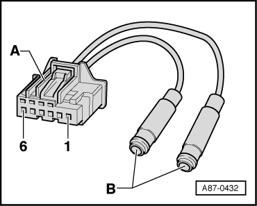
Note
The line can be connected to a 12 V power supply (for example, a 12 V battery) via the banana couplings -B- (using, for example, leads from the Connector Test Set -VAG1594D-).
Technical Data
Refrigerant R134a Capacities
| Manufacturer | Total capacity |
| Delphi | Refer to → Fluid Capacity Tables; Rep. Gr.03 |
| Denso | Refer to → Fluid Capacity Tables; Rep. Gr.03 |
| Sanden | Refer to → Fluid Capacity Tables; Rep. Gr.03 |
Refrigerant Oil
There are different refrigerant oils depending on the manufacturer. Refer to the Parts Catalog for the part number.Refrigerant oil attracts moisture. Because of this, refrigerant oil that was stored for long periods of time in an open container is unusable.
- Close opened containers immediately after use to prevent moisture contamination.
| Type | Total capacity |
| 6CVC140; Delphi | Refer to → Fluid Capacity Tables; Rep. Gr.03 |
| 6SEU14; Denso | Refer to → Fluid Capacity Tables; Rep. Gr.03 |
| 7SEU17C; Denso | Refer to → Fluid Capacity Tables; Rep. Gr.03 |
| 11 PXE14; Sanden | Refer to → Fluid Capacity Tables; Rep. Gr.03 |
| 07 PXE17 and 06 PXE17; Sanden | Refer to → Fluid Capacity Tables; Rep. Gr.03 |
Oil Distribution
The oil, which is located in the A/C compressor oil pan before the initial switching on of the A/C system, is distributed through the refrigerant circuit as follows:
- A/C compressor: approximately 50%
- Condenser: approximately 10%
- Suction hose: approximately 10%
- Evaporator: approximately 20%
- Receiver/dryer: approximately 10%
Special Tools
Special tools and workshop equipment required
- Connector Test Set -VAG1594D-
- Vehicle Diagnostic Tester


See More:
Volkswagen Tiguan Service and Repair Manual > Steering: Steering Column and Steering Wheel
Overview - Steering Column
Note
Welding and straightening work on supporting or wheel carrying
components of suspension is not permitted.
Always replace self-locking nuts.
Always replace corroded bolts/nuts.
Steering Column Crossmember
With mounting bracket
Steering Column
Removi ...
Volkswagen Tiguan Owners Manual
Volkswagen Tiguan Service and Repair Manual
- Body exterior
- Body Interior
- General Paint Information
- Paint
- Brake System
- Suspension, Wheels, Steering
- Wheel and Tire Guide
- Towing Guide
- Wheel and Tire Guide General Information
- Communication
- Electrical Equipment General Information
- Electrical Equipment from 06/2011
- Heating, Ventilation and Air Conditioning
- Refrigerant R134a Servicing
- 6-Speed Manual Transmission 02Q, OBB, and OFB
