Volkswagen Tiguan Service and Repair Manual: Wheel/Tire Vibration, Causes and Solution
Vibration Causes
There are many causes for vibration. Vibration can also be caused by tire wear, among other things. Tire wear caused by driving does not always develop evenly over the entire tread. Due to this, a slight imbalance develops which disturbs the smoothness of the formerly accurately balanced wheel.
This slight imbalance cannot yet be felt in the steering wheel, but it is present. It increases the tire wear and consequently reduces the service life of the tire.
Recommendation
In order to guarantee over the entire service life of a tire a
- optimal safety,
- optimal smoothness and
- uniform wear
it is recommended that wheels/tires be balanced at least two times within the tire service life.
Balancing
Before beginning balancing, the following requirements must be fulfilled.
- Tire inflation pressure must be OK.
- The tire tread must not be worn down on one side and should be at least 4 mm deep.
- The tires must not have any damage such as cuts, holes, foreign bodies, etc.
- The suspension, steering, tie rods and damper must be in proper working order.
- A road test has been performed.
Road Test, Performing Before Balancing
If a vehicle comes to the workshop with the complaint "vibration", a road test must be performed before balancing the wheels.
- That way, information about the type of vibration can be obtained.
- Observe at which speed range the disturbance takes place.
| Component Location of Tire | Identification with ... |
| Left front tire | LF |
| Right front tire | RF |
| Left rear tire | LR |
| Right rear tire | RR |
- Raise the vehicle on the platform immediately after the road test.
- Mark the installation position on the tire.
- Remove wheels from vehicle.
- Balance the wheels.
Stationary Balancing Machine
- Test drive performed.
Tension Wheel on Balancing Machine
Note
Please keep in mind that cleanliness is extremely important when balancing, as it is when performing any other repair work. Only then can a proper result be obtained!
Dirt and rust in the area of the contact surfaces and centering of the wheel distort the result.
- Clean contact surfaces, centering seat and wheel disc using the Pneumatic Brush Grinder Set -VAS6446- before tensioning wheel on balancing machine! Refer to Workshop Equipment, Catalog.
Note
It is very important that the wheel balancing machine uses the correct system for centering and tensioning the tires when replacing them. Reference the information for the Wheel Balancing Machine Centering System before beginning any work. Refer to Workshop Equipment, Catalog.
- Tension the wheel with the tire on the balancing machine.
Note
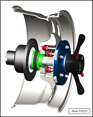
- To mount wheel on wheel balancer, use for example Wheel Centering System Adapter -VAS5271-.
- This way a 100% centering of the wheel and gentle mounting is possible!
- It is not possible to center it 100% on balancing machine with conical tensioners.
- With a deviation of 0.1 mm outside the center, there is an imbalance of 10 grams on the wheel/tire.
Wheel/Tire Balancing Procedure
- Let the wheel and tire rotate on the wheel balancer.
- Check the run of the characteristic lines on the sidewall of the tire in the area of the rim flange.
- Check the tire wear pattern while the wheel and tire are rotating.
Note
In the event of one-sided wear, flat spots from braking or severe wear spots, smooth running cannot be achieved by balancing. In this case, the tire must be replaced.
- Check the run-out of the wheel and tire. If the wheel with tire runs untrue although there are no flat spots, a radial or lateral run-out may be the cause.
- Check wheel with tire for radial- and lateral run-out.
- If the radial and lateral run-out are within the specified tolerance, balance the wheel and tire.
Note
- Do not use more than 60 grams of weight per wheel.
- If more weight is necessary, a smoother running can achieved by matched mounting of the tire. Matched mounting of tire.
- The display in the balancing machine should show 0 grams.
- Hunter RFT33VAG Road Force Touch Wheel Balancer -VAS6230B4- can be inserted as an alternative to matching.
- Bolt the wheel to the vehicle.
- First, tighten the lowest wheel bolt by hand to approximately 30 Nm.
- Now tighten the remaining wheel bolts diagonally also to about 30 Nm. This process centers the wheel on the wheel hub.
- Put the vehicle on its wheels.
- Now use a torque wrench to tighten the wheel bolts diagonally to the specified tightening specification.
Road Test, Performing
- Perform a road test after balancing wheel/tire.
If a vibration is still detected during the road test, the cause may be due to tolerance in the wheel centering.
The component tolerances of wheels and wheel hubs can be additive in unfavorable cases. Vibration can result from this. This can be eliminated using a finish balancer.
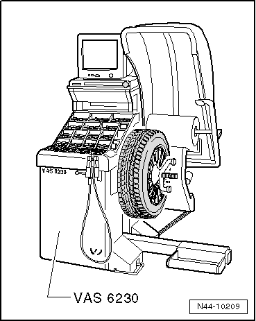
Hunter RFT33VAG Road Force Touch Wheel Balancer -VAS6230B4-
Expanded functions can be performed using Hunter RFT33VAG Road Force Touch Wheel Balancer -VAS6230B4- in addition to the previously known balancers.
A special characteristic of this system is testing the radial force of wheel/tire during rolling.
For this purpose, a roller presses a force of approximately 635 kg against the wheel. This simulates the tire contact force against the street surface while driving.
Tire contact forces fluctuate due to radial- and lateral run-out and differing rigidity in the tires.
The Hunter RFT33VAG Road Force Touch Wheel Balancer -VAS6230B4- detects and stores the position of the maximum measured radial force in the tires. After that, the position of smallest dimension between rim flange and disc wheel center is measured.
Finish Balancer
Note
- Working with a Finish Balancer requires instruction from the manufacturer of the balancer.
- For the balancing, the wheels of the tractive axle are set upon the turntable sensors, for example, front wheels for Front Wheel Drive (FWD) and all 4 wheels for All Wheel Drive (AWD).
If it is determined when balancing on the vehicle the remaining imbalance is more than 20 grams, the wheel should be rotated on the wheel hub.
- Mark the point at which the imbalance is indicated.
- Afterwards, unbolt the wheel and rotate its position on the wheel hub so that the marking points downward.
Note
The wheel hub must not turn during this procedure.
- First, tighten the lowest wheel bolt by hand to approximately 30 Nm.
- Now tighten the remaining wheel bolts diagonally also to about 30 Nm. This process centers the wheel properly on the wheel hub.
- Check again whether the imbalance is less than 20 grams using the finish balancer.
Note
The imbalance should not be smaller than 20 grams under any circumstances before changing balance weight.
- Remove the wheel bolts again if necessary.
- Rotate the wheel relative to the wheel hub once more by one or two wheel bolt holes.
- Tighten the wheels using the method described above.
Note
The imbalance should only be reduced by changing balance weight if the imbalance is less than 20 grams.
- Balance the wheels until the imbalance is below five grams.
- Tighten the wheel bolts to the specified tightening specification if you have not already done so.
WARNING
Always tighten the wheel bolts to the specified tightening specification using a torque wrench.
Tire and Wheel Radial and Lateral Run-Out
Radial and lateral run-out occur when the wheel and tire are not running precisely true.For technical reasons, 100% true running is not possible.
Therefore the manufacturers of these components allow a precisely specified tolerance.Mounting the tire in a unfavorable position on the wheel can be the cause for exceeding the maximum allowed tolerance for wheel with tire.
The table shows the maximum permissible tolerance values for the wheel with mounted tire.Tolerances for radial and lateral run-out of disc wheel with tire
| Wheel with tire | Radial run-out (mm) | Lateral run-out (mm) |
| Passenger Vehicle | 0.9 | 1.1 (1.3 near the lettering) |
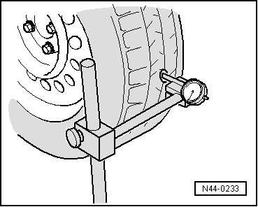
Wheels and Tires, Checking Radial and Lateral Run-Out with Tire Dial Gauge -VAG1435-
Checking Lateral Run-Out
- Load the Tire Dial Gauge -VAG1435- approximately 2 mm.
- Set up Tire Dial Gauge -VAG1435- on the side wall of the tire.
- Slowly rotate the wheel.
- Note the smallest and the largest dial readings.
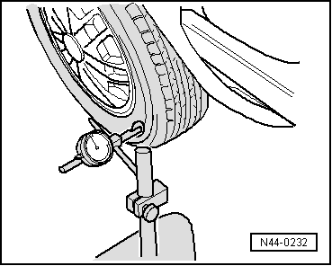
Note
If the difference is greater than 1.3 mm, the lateral run-out is too great.
In this case, lateral run-out can be reduced by matched mounting of the tire.
Peak values on the Tire Dial Gauge -VAG1435- due to small irregularities in the rubber may be disregarded.
Checking Radial Run-Out
- Load the Tire Dial Gauge -VAG1435- approximately 2 mm.
- Set up Tire Dial Gauge -VAG1435- on the tire tread.
- Slowly rotate the wheel.
- Note the smallest and the largest dial readings.
Note
If the difference is greater than 1 mm, the radial run-out is too great.
In this case, radial run-out can be reduced by matched mounting of the tire.
Disc Wheel, Checking Radial and Lateral Run Out
- Mount the disc wheel on theWheel Balancer.
- Use the Wheel Centering System Adapter -VAS5271-.
- Load the Tire Dial Gauge -VAG1435- approximately 2 mm.
- Slowly turn the disc wheel.
- Note the smallest and the largest dial readings.
H - Radial Run-Out
- Compare determined value with specifications.
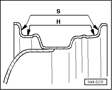
Note
Peak values on the Tire Dial Gauge -VAG1435- due to small irregularities may be disregarded.
Specifications for Radial and Lateral Run-Out on Disc Wheel
| Disc Wheel | Radial Run-Out (mm) | Lateral Run-Out (mm) |
| Steel wheel | 0.5 | 0.5 |
| Light alloy wheel | 0.5 | 0.8 |
Note
If the measured value exceeds the specified value, no acceptable smooth running can be attained.
Matching
General Information
If radial or lateral run-out from wheel or tire meet each other, the untrue running of the wheel and tire is increased.
For technical reasons, 100% true running is not possible.
Drive the tires until they are warm before matching them to the tires already on the vehicle. This eliminates flat spots from standing which may exist.
Work Procedure for Match-Mounting
- Let the air out of the tire.
- Press the tire beads off the rim flanges.
- Coat the tire beads all around with Tire Mounting Paste.
- Rotate the tire 180º relative to the disc wheel.
- Inflate the tire to approximately 4 bar.
- Tension wheel with tire on balancing machine.
- Check the run-out or the radial and lateral run-out, as necessary.
Note
- If the radial and lateral run-out value is not exceeded, the wheel can be balanced to 0 grams. Specifications.
- If the radial and lateral run-out lies outside the specified values, the tire must be turned again.
- Let the air out of the tire and press the tire beads off the rim flanges.
- Rotate the tire 90º (one quarter turn) relative to the disc wheel.
- Inflate the tire to 4 bar (58 psi) and check for true running.
Note
- If the radial and lateral run-out value is not exceeded, the wheel can be balanced to 0 grams.
- If the radial and lateral run-out is still outside the specified values, the wheel must be turned again.
- Press the tire beads off the rim flanges.
- Rotate the tire 180º (one half turn) relative to the disc wheel.
If the values for radial or lateral run-out are still outside the specified values, check the wheel for radial and lateral run-out.
If the measured values for radial and lateral run-out of the wheel disc are within the specified values, then the tire has excessive radial or lateral run-out. In this case, the tire must be replaced.
Note
- Assembly paste from mounting tires is located between tires and rim flanges.
- Avoid strong braking or acceleration maneuvers during the first 100 to 200 km (62.1 to 124.2 miles). Otherwise, the tires can rotate on the rims and the work done would then be undone!
 Wheel, Changing and Mounting
General Information
WARNING
The secure seating of the wheel bolts and the wheels is only ensured if the
instructions and checks below are followed.
Note
After removing or installing one or multiple t ...
 Driver Assistance Systems Front Camera -R242-
General Information
Note
If the camera can no longer recognize the lane markings due to poor
visibility, this could be caused by:
The camera visual field is dirty or icy. If that is the problem, it ...
See More:
Volkswagen Tiguan Owners Manual > Center console overview: Lower center console
Fig. 7 Vehicles without Keyless Access:
Overview of center console lower section.
Key to ⇒ Fig. 7 :
Button for:
Electronic parking brake
⇒ Braking, stopping, and parking
Cup holders
Card holder ⇒ Storage areas
Levers for:
Manual transmission ⇒ Shift ...
Volkswagen Tiguan Owners Manual
Volkswagen Tiguan Service and Repair Manual
- Body exterior
- Body Interior
- General Paint Information
- Paint
- Brake System
- Suspension, Wheels, Steering
- Wheel and Tire Guide
- Towing Guide
- Wheel and Tire Guide General Information
- Communication
- Electrical Equipment General Information
- Electrical Equipment from 06/2011
- Heating, Ventilation and Air Conditioning
- Refrigerant R134a Servicing
- 6-Speed Manual Transmission 02Q, OBB, and OFB
