Volkswagen Tiguan Service and Repair Manual: Subframe, Transverse Link and Tie Rods from MY 2011, FWD
Overview - Subframe, Transverse Link and Tie Rods from MY 2011, FWD
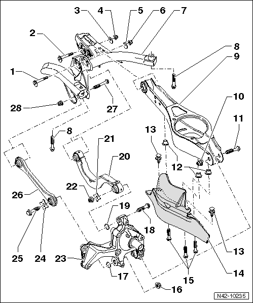
- Eccentric Bolt
- For camber setting
- Perform a vehicle alignment after loosening.
- Eccentric Bollt
- For toe setting
- Perform a vehicle alignment after loosening.
- Eccentric Washer
- Inner bore with tab
- Nut
- 95 Nm
- Always replace if removed
- Self-locking
- M12 x 1.5
- Always tighten the threaded connections in curb weight position.
- Eccentric Washer
- Inner bore with tab
- Nut
- 95 Nm
- Always replace if removed
- M12 x 1.5
- Self-locking
- Always tighten the threaded connections in curb weight position.
- Subframe
- Bolt
- 90 Nm +90º
- Always replace if removed
- M12 x 1.5 x 95
- Lower Transverse Link
- Removing and installing.
- Nut
- 90 Nm +90º
- Always replace if removed
- M12 x 1.5
- Self-locking
- Always tighten the threaded connections in curb weight position.
- Bolt
- Always replace if removed
- Threaded Rivet
- M6
- Expanding Rivet
- Stone Chip Protection
- Allocation. Refer to the Parts Catalog.
- Bolt
- 8 Nm
- Nut
- 130 Nm + 90º
- Always replace if removed
- M14 x 1.5
- Self-locking
- Washer
- Bolt
- 130 Nm + 90º
- Always replace if removed
- Always tighten the threaded connections in curb weight position.
- Washer
- Upper Transverse Link
- Removing and installing.
- Washer
- Nut
- M14 x 1.5
- Self-locking
- Always replace if removed
- Always tighten the threaded connections in curb weight position.
- Wheel Bearing Housing
- Removing and installing.
- Washer
- Bolt
- Always replace if removed
- Always tighten the threaded connections in curb weight position.
- Tie Rod
- Closed in direction of travel (the right and left tie rods are different)
- Allocation. Refer to the Parts Catalog.
- Removing and installing.
- Bolt
- Always replace if removed
- Nut
- 90 Nm +90º
- Always replace if removed
- M12 x 1.5
- Self-locking
- Always tighten the threaded connections in curb weight position.
Overview - Left Rear Level Control System Sensor -G76-, FWD
Note
- Overview - Left Rear Level Control System Sensor -G76- Adaptive Chassis DCC, FWD.
- Vehicle level sensor is available as replacement part only complete with coupling rod and upper and lower retaining plates.
- Replacing with subframe installed.
- Headlamp Range Control Module -J431-
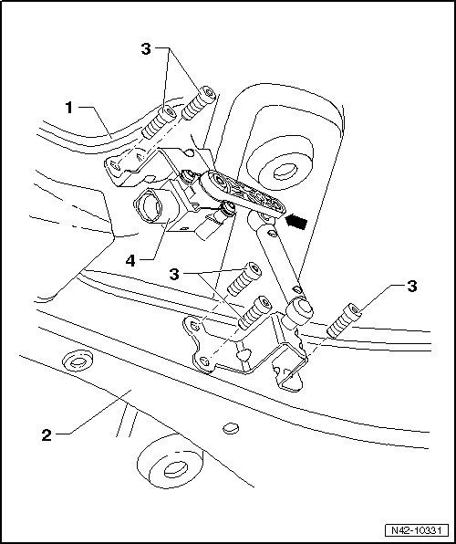
- Subframe
- Lower Transverse Link
- Bolt
- 5 Nm
- M5 x 20
- Left Rear Level Control System Sensor -G76-
- Complete with attachments
- Lever -arrow- must point toward vehicle exterior
- Replace in vehicle.
- After replacing, perform basic setting of the headlamps
Headlamps basic setting. Refer to Parts Catalog.
Left Rear Level Control System Sensor -G76-, Removing and Installing
Note
Left Rear Level Control System Sensor -G76- for adaptive chassis DCC, FWD, Removing and installing.
Special tools and workshop equipment required
- Torque Wrench 1331 5-50Nm -VAG1331-
Removing
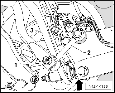
- Disconnect the connector -1-.
- Remove the bolts -2- from the lower transverse link.
- Remove bolts -arrows- from the subframe.
- Remove Left Rear Level Control System Sensor -G76-.
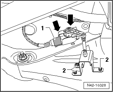
Installing
Install in reverse order of removal. Note the following:
The Left Rear Level Control System Sensor -G76- lever must point toward the outside of the vehicle.
- After replacing, perform a headlamp basic setting Vehicle Diagnostic Tester, in "Guided Fault Finding" function
Tightening Specifications
| Component | Tightening Specification |
| Left Rear Level Control System Sensor -G76- to lower transverse link and subframe | 5 Nm |
Rear Axle, Removing and Installing
Special tools and workshop equipment required
- Torque Wrench 1332 40-200Nm -VAG1332-
- Engine and Gearbox Jack -VAS6931-
Removing the Subframe and its Attachments
- Remove the wheels.
- Remove the coil springs.
- Disconnect the electric connections between the rear axle and the body.
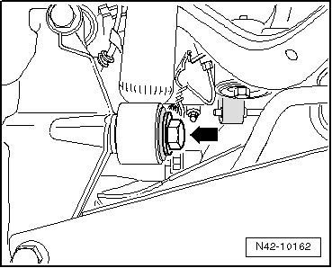
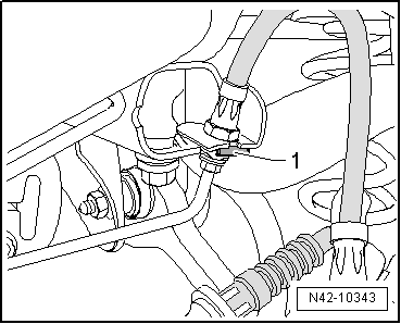
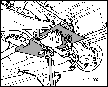
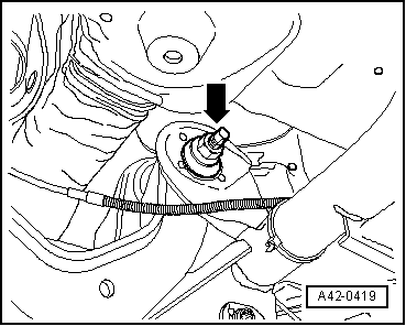
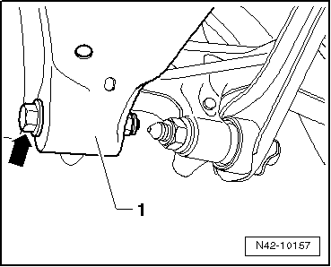
- Remove the bolt -arrow-.
- Remove the hose retainer -1- on both sides of the vehicle.
- Disconnect the parking brake connectors from the brake caliper.
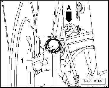
- Remove retainer -1-, pressing out inner pins of rivets -arrows A-.
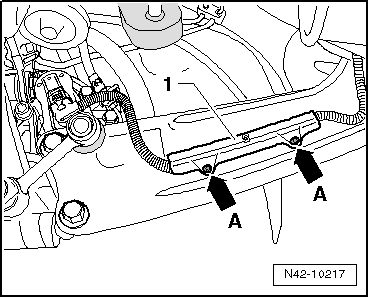
- Remove line -1- at mounting bracket -arrow A-.
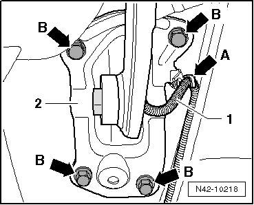
- Mark installation position of mounting bracket -2- on body.
- Remove the bolts -B arrows-.
- Disconnect Left Rear Level Control System Sensor -G76- connector.
- Now secure vehicle on both sides to lifting arms on hoist with Tensioning Strap -T10038-.
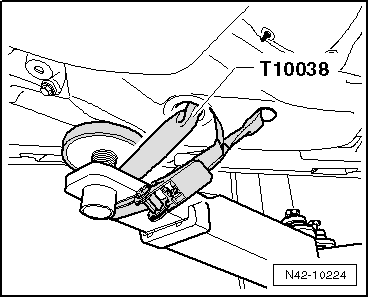
WARNING
If vehicle is not secured, it could slide off of hoist.
- Place the Engine/Gearbox Jack - VAG1383A- with Universal Support Plate -VAG1359/2- below subframe and secure with strap.
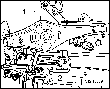
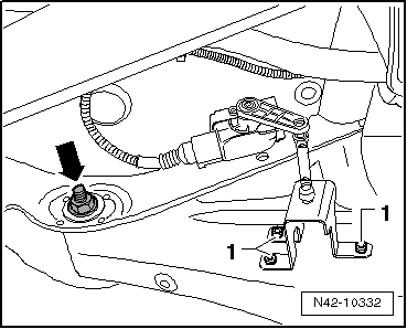
- Remove hex head bolt -1 or 2- on both sides.
Note
Only the left side of the vehicle is shown in the illustration.
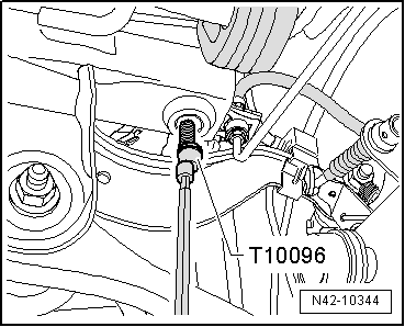
To secure the subframe, Locating Pins -T10096- must be screwed in one after the other on both sides of the vehicle at positions -1 and 2-.
- Location position of subframe with Locating Pins -T10096-.
Note
Locating Pins -T10096- may only be tightened to a maximum of 20 Nm, since otherwise the threads of the locating bolts will be damaged.
- Replace the bolts of the subframe one after the other on both sides using Locating Pins -T10096- and tighten them to 20 Nm.
The subframe position is now secured.
- Carefully lower the subframe with its components 30 mm maximum.
Note
When lowering, ensure the brake lines and electrical lines have adequate clearance.
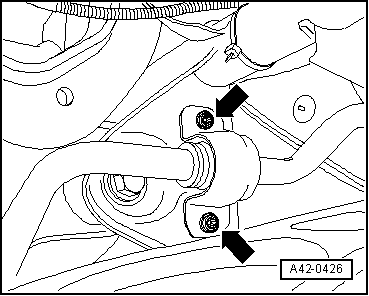
- Remove the brake line -1- from the clips -arrows-.
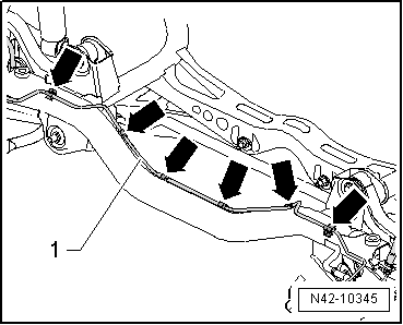
Note
- When doing this, the clips will be destroyed and must be replaced.
- For illustrative purposes, the illustration shows the subframe removed and from the top.
- Lower subframe with attachments.
Note
When lowering, ensure the brake lines and wires have sufficient clearance.
Installing the Subframe with Attachments
Install in reverse order of removal. Note the following when doing so:
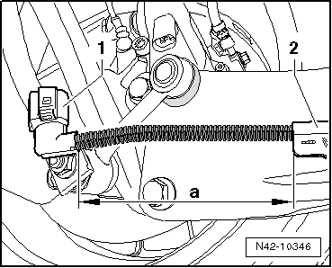
- When installing the wires for the electrical parking brake, make sure the dimension -a- between the connector -1- and the retainer -2- is exact.
Dimension -a- = 150 mm
- Bleed the brake system.
Tightening Specifications
| Component | Tightening Specification |
Subframe to body
|
90 Nm + 90º |
| Shock absorber to wheel bearing housing. | 180 Nm |
Mounting bracket to body
|
50 Nm + 45º |
Upper Transverse Link, Removing and Installing
Special tools and workshop equipment required
- Torque Wrench 1332 40-200Nm -VAG1332-
Removing
- Remove the wheel.
- Remove coil spring.
- Disengage wire -arrow a- for speed sensor from upper transverse link.
- Remove the bolt -1-.
- Mark, for example using a felt-tip marker, position of eccentric bolt -arrow- to subframe.
- Remove the bolt -arrow-.
- Remove upper transverse link.
Installing
- Insert the upper transverse link into the vehicle and tighten the bolts by hand.
The bolted connections of the tie rod must only be fastened when the dimension "a" is achieved.
- Bolt upper transverse link to subframe and tighten new nut.
- Note applied marking of eccentric bolt -arrow- to subframe.

- Tighten the bolt -1- on the upper transverse link.
Note
Make sure a washer is installed between the transverse link and the wheel bearing housing.
- Engage speed sensor wire -arrow- on upper transverse link.
- Install coil spring.
- Install the wheel and tighten.
- Perform vehicle alignment.

Tightening Specifications
| Component | Tightening Specification |
Upper transverse link to
wheel bearing housing
|
130 Nm + 90º |
Upper transverse link to
subframe
|
95 Nm
|
Lower Transverse Link, Removing and Installing
Special tools and workshop equipment required
- Torque Wrench 1332 40-200Nm -VAG1332-
Removing
- Remove the wheel.
- Remove coil spring.
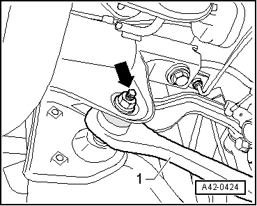
- Remove bolt -arrow- for lower transverse link -1-.

Vehicles with DCC Adaptive Chassis and Dynamic Headlamp Range Control
- Remove the bolts -1- from the lower transverse link.
Note
On vehicle with DCC adaptive chassis, the Left Rear Level Control System Sensor -G76- is secured on the bottom of the transverse link with two bolts.
Continuation for All Vehicles
- Mark, for example using a felt-tip marker, position of eccentric bolt -arrow- to subframe.
- Disengage rear exhaust system and lower.
- Remove the bolt -arrow-.
- Remove lower transverse link.

Installing
- Insert lower transverse link into vehicle and tighten the bolts by hand.
The bolted connections of the tie rod must only be fastened when the dimension "a" is achieved.
- Connect the upper transverse link to the subframe and tighten the new nut -arrow- to the tightening specification only.
- Check the marking that was made on the eccentric bolt for aligning with the subframe.
Vehicles with DCC Adaptive Chassis and Dynamic Headlamp Range Control
- Install the bolts -1- to the lower transverse link.
Continuation for All Vehicles
- Tighten bolt -arrow- for lower transverse link -1-.
- Install coil spring.
- Install the wheel and tighten.
- Perform vehicle alignment.
Tightening Specifications
| Component | Tightening Specification |
Lower transverse link to
wheel bearing housing
|
90 Nm + 90º |
Lower transverse link to
subframe
|
95 Nm |
| Left Rear Level Control System Sensor -G76- to lower transverse link | 5 Nm |
Tie Rod, Removing and Installing
Special tools and workshop equipment required
- Torque Wrench 1331 5-50Nm -VAG1331-
- Torque Wrench 1332 40-200Nm -VAG1332-
Removing
- Remove the wheel.
- Remove coil spring.
- Remove the nut -1- and pull the coupling rod -2- out of the stabilizer bar.
- Remove bolt -arrow- for tie rod -3-.
- Remove the bolts -arrows- for the stabilizer bar clamp.
- Remove the nut -arrow- and remove bolt toward rear.
- Remove tie rod -1-.
Installing
- Insert tie rod into vehicle and tighten the bolts by hand.
Note
The tie rods must be closed in the direction of travel.
The bolted connections of the tie rod must only be fastened when the dimension "a" is achieved.
- Fasten the tie rod -1- to the subframe and tighten the new nut -arrow-.

- Tighten bolts -arrows- for stabilizer clamp.

- Tighten bolt -arrow- for tie rod -3-.
Note
Make sure a washer is installed between the tie rod and the wheel bearing housing.
- Insert coupling rod -2- into stabilizer and tighten nut -1-.
- Install coil spring.
- Install the wheel and tighten.
- Perform vehicle alignment.

Tightening Specifications
| Component | Tightening Specification |
Tie rod to steering
knuckle
|
130 Nm + 90º |
Tie rod to subframe
|
90 Nm + 90º |
Stabilizer bar to
subframe
|
25 Nm + 45º |
Stabilizer bar to coupling rod
|
40 Nm |
 Transverse Links and Tie Rods, through MY 2010, FWD
Overview - Transverse Links and Tie Rods, through MY 2010, FWD
Eccentric Bolt
For camber setting
Perform a vehicle alignment after loosening.
Nut
95 Nm
Always replace if removed
M1 ...
 Wheel Bearing Housing, Trailing Arm, FWD
Overview - Wheel Bearing Housing, Trailing Arm, FWD
Cover
Mounting Bracket
Coupling Rod
Connects stabilizer to trailing link/wheel bearing housing
Bolt
90 Nm + 45º
Always replace if ...
See More:
Volkswagen Tiguan Service and Repair Manual > Wiring Harness and Connector Repairs: Wiring Harnesses, Repairing
Airbag and Belt Tensioner Wire Repair Information
Note
Observe general notes for repairs on the vehicle electrical system.
In addition to the general repairs on wiring harnesses, the following methods
and instructions must be observed for repairs on airbag- and seat belt tensioner
wires
WARNING
...
Volkswagen Tiguan Owners Manual
Volkswagen Tiguan Service and Repair Manual
- Body exterior
- Body Interior
- General Paint Information
- Paint
- Brake System
- Suspension, Wheels, Steering
- Wheel and Tire Guide
- Towing Guide
- Wheel and Tire Guide General Information
- Communication
- Electrical Equipment General Information
- Electrical Equipment from 06/2011
- Heating, Ventilation and Air Conditioning
- Refrigerant R134a Servicing
- 6-Speed Manual Transmission 02Q, OBB, and OFB
