Volkswagen Tiguan Service and Repair Manual: Transverse Links and Tie Rods, through MY 2010, FWD
Overview - Transverse Links and Tie Rods, through MY 2010, FWD
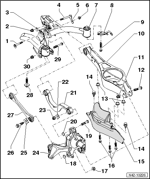
- Eccentric Bolt
- For camber setting
- Perform a vehicle alignment after loosening.
- Nut
- 95 Nm
- Always replace if removed
- M12 x 1.5
- Self-locking
- Always tighten the threaded connections in curb weight position.
- Eccentric Washer
- Inner bore with tab
- Eccentric Bolt
- For toe setting
- Perform a vehicle alignment after loosening.
- Eccentric Washer
- Inner bore with tab
- Nut
- 95 Nm
- Always replace if removed
- Self-locking
- M12 x 1.5
- Always tighten the threaded connections in curb weight position.
- Subframe
- Removing and installing.
- Servicing.
- Bracket for Rear Muffler
- Bolt
- 90 Nm +90º
- Always replace if removed
- M12 x 1.5 x 110
- Lower Transverse Link
- Removing and installing.
- Nut
- 90 Nm +90º
- Always replace if removed
- M12 x 1.5 x 75
- Self-locking
- Always tighten the threaded connections in curb weight position.
- Bolt
- Always replace if removed
- Threaded Rivet
- M6
- Expanding Rivet
- Stone Chip Protection
- Allocation. Refer to the Parts Catalog.
- Hex Bolt
- 8 Nm
- M6 x 12
- Nut
- Self-locking
- Always replace if removed
- Washer
- Bolt
- 130 Nm + 90º
- Always replace if removedM14 x 1.5 x 115
- Always tighten the threaded connections in curb weight position.
- Washer
- Upper Transverse Link
- Removing and installing.
- Washer
- Nut
- Self-locking
- Always replace if removed
- Always tighten the threaded connections in curb weight position.
- Wheel Bearing Housing
- Removing and installing.
- Washer
- Bolt
- 130 Nm + 90º
- Always replace if removed
- M14 x 1.5 x 115
- Always tighten the threaded connections in curb weight position.
- Tie rod
- There are different versions.
- Closed in direction of travel (the right and left tie rods are different)
- Opened downward (the right and left tie rods are the same)
- It is possible to interchange
- Pay attention to the allocation of the trailing arms when replacing them.
- Removing and installing.
- Bolt
- 90 Nm +90º
- M12 x 1.5 x 95
- Always replace if removed
- Bolt
- M12 x 1.5 x 90
- Always replace if removed
- Always tighten the threaded connections in curb weight position.
- Nut
- 90 Nm +90º
- Always replace if removed
- Self-locking
- Always tighten the threaded connections in curb weight position.
Overview - Left Rear Level Control System Sensor -G76-, FWD
Note
- Overview - Left Rear Level Control System Sensor -G76- Adaptive Chassis DCC, FWD.
- Vehicle level sensor is available as replacement part only complete with coupling rod and upper and lower retaining plates.
- Replacing with subframe installed.
- Headlamp Range Control Module -J431-
- Subframe
- Lower Transverse Link
- Bolt
- 5 Nm
- M5 x 20
- Left Rear Level Control System Sensor -G76-
- Complete with attachments
- Lever -arrow- must point toward vehicle exterior
- Replace in vehicle.
- After replacing, perform basic setting of the headlamps
Headlamps basic setting. Refer to Vehicle Diagnostic Tester, in "Guided Fault Finding" function.
Left Rear Level Control System Sensor -G76-, Removing and Installing
Note
Left Rear Level Control System Sensor -G76- for adaptive chassis DCC, FWD, Removing and installing.
Special tools and workshop equipment required
- Torque Wrench 1331 5-50Nm -VAG1331-
Removing
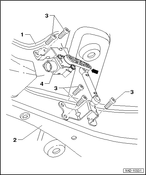
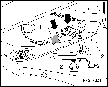
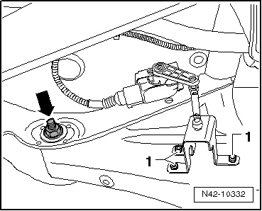
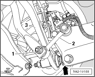
- Disconnect the connector -1-.
- Remove the bolts -2- from the lower transverse link.
- Remove bolts -arrows- from the subframe.
- Remove Left Rear Level Control System Sensor -G76-.
Installing
Install in reverse order of removal. Note the following:
The Left Rear Level Control System Sensor -G76- lever must point toward the outside of the vehicle.
- After replacing, perform a headlamp basic setting Vehicle Diagnostic Tester, in "Guided Fault Finding" function
Tightening Specifications
| Component | Tightening Specification |
| Left Rear Level Control System Sensor -G76- to lower transverse link and subframe | 5 Nm |
Upper Transverse Link, Removing and Installing
Special tools and workshop equipment required
- Torque Wrench 1332 40-200Nm -VAG1332-
Removing
- Remove the wheel.
- Remove coil spring.
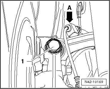
- Unhook speed sensor wiring -arrow A- from the upper transverse link.
- Remove the bolt -1-.

- Mark, for example using a felt-tip marker, position of eccentric bolt -arrow- to subframe.
- Remove the bolt -arrow-.
- Remove upper transverse link.

Installing
- Insert the upper transverse link into the vehicle and tighten the bolts by hand.
Only bolt on transverse link if dimension "a" is reached.
- Bolt upper transverse link to subframe and tighten new nut.
- Note applied marking of eccentric bolt -arrow- to subframe.

- Tighten the bolt -1- on the upper transverse link.
Note
Make sure that washer is installed between bolt and wheel bearing housing.
- Hook speed sensor wiring -arrow A- in at the upper transverse link.
- Install coil spring.
- Install the wheel and tighten.
- Perform vehicle alignment.
Tightening Specifications
| Component | Tightening Specification |
Upper transverse link to
wheel bearing housing
|
130 Nm + 90º |
Upper transverse link to
subframe
|
95 Nm
|
Lower Transverse Link, Removing and Installing
Special tools and workshop equipment required
- Torque Wrench 1332 40-200Nm -VAG1332-
Removing
- Measure dimension from wheel center to lower edge of wheel housing.
- Remove the wheel.
- Remove coil spring.
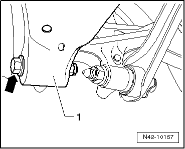
- Remove bolt -arrow- for lower transverse link -1-.

Vehicles with Automatic Headlamp Range Control
- Remove the bolts -1- from the lower transverse link.
Continuation for All Vehicles
- Mark, for example using a felt-tip marker, position of eccentric bolt -arrow- to subframe.
- Disengage rear exhaust system and lower.
- Remove the bolt -arrow-.
- Remove lower transverse link.
Installing
- Insert lower transverse link into vehicle and tighten the bolts by hand.
Only bolt on transverse link if dimension "a" is reached.
- Connect the upper transverse link to the subframe and tighten the new nut -arrow- to the tightening specification only.
- Note applied marking of eccentric bolt -arrow- to subframe.
- Suspend rear exhaust system.

Vehicles with Automatic Headlamp Range Control
- Install the bolts -1- to the lower transverse link.
Continuation for All Vehicles
- Tighten bolt -arrow- for lower transverse link -1-.
- Install coil spring.
- Install the wheel and tighten.
- Perform vehicle alignment.
Tightening Specifications
| Component | Tightening Specification |
Lower transverse link to
wheel bearing housing
|
90 Nm + 90º |
Lower transverse link to
subframe
|
95 Nm |
| Left Rear Level Control System Sensor -G76- to lower transverse link | 5 Nm |
Tie Rod, Removing and Installing
Special tools and workshop equipment required
- Torque Wrench 1331 5-50Nm -VAG1331-
- Torque Wrench 1332 40-200Nm -VAG1332-
Removing
- Remove the wheel.
- Remove coil spring.
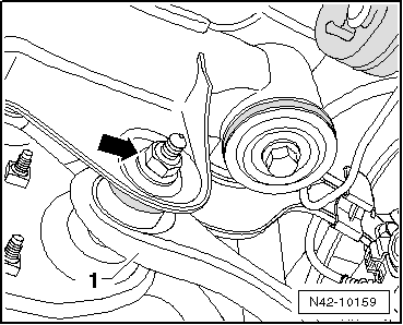
- Remove the nut -1- and pull the coupling rod -2- out of the stabilizer bar.
- Remove bolt -arrow- for tie rod -3-.

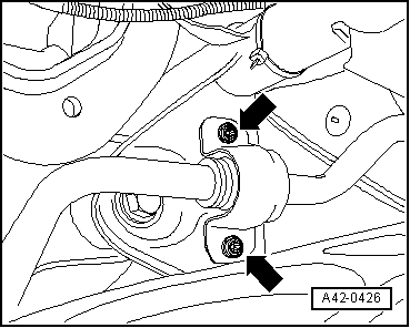
- Remove the bolts -arrows- for the stabilizer bar clamp.
- Remove the nut -arrow- and remove bolt toward rear.
- Remove tie rod -1-.
Installing
Caution
- Pay attention to the different trailing arm versions when replacing the tie rod.
- Note the allocation of the tie rods for the trailing arms.
- Insert tie rod into vehicle and tighten the bolts by hand.
Note
Pay attention to the different versions of the tie rods: open underneath or closed in direction of travel.
The bolted connections of the tie rod must only be fastened when the dimension "a" is achieved.
- Fasten the tie rod -1- to the subframe and tighten the new nut -arrow-.

- Tighten bolts -arrows- for stabilizer clamp.

- Tighten bolt -arrow- for tie rod -3-.
Note
Make sure that washer is installed between nut and wheel bearing housing.
- Insert coupling rod -2- into stabilizer and tighten nut -1-.
- Install coil spring.
- Install the wheel and tighten.
- Perform vehicle alignment.
Tightening Specifications
| Component | Tightening Specification |
Tie rod to steering
knuckle
|
130 Nm + 90º |
Tie rod to subframe
|
90 Nm + 90º |
Stabilizer bar to
subframe
|
25 Nm + 45º |
Stabilizer bar to coupling rod
|
40 Nm |
Tie Rods for Trailing Arms, FWD and AWD, Allocation
Note
The current production is now using the reinforced trailing arms. The old trailing arms are no longer available as a replacement part.
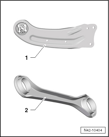
Trailing Arm Characteristics
- Standard trailing arm
- Reinforced trailing arm
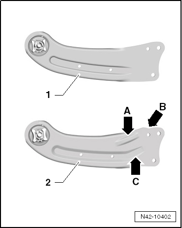
The reinforced trailing arm has the following distinguishing features:
Pfeil A - Additional reinforcement
Pfeil B - Additional opening
Pfeil C - Lengthened rib
- Interchanging the trailing arms is permitted
- Note the different tie rod versions when replacing the trailing arm.
- Allocation of the trailing arms to the tie rods.
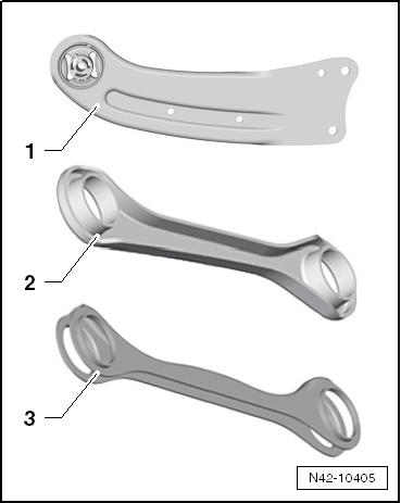
Tie Rod Characteristics
- Reinforced tie rod closed in direction of travel
- Standard tie rod open downward
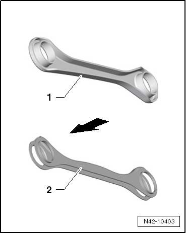
- The reinforced tie rod is different on the right and left sides.
- The standard tie rod is the same on the left and right sides.
- Arrow indicates direction of travel.
- Interchanging the tie rods is permitted
- Pay attention to the different trailing arm versions when replacing the tie rod.
- Allocation of the trailing arms to the tie rods.
Note the Allocation of the Tie Rods for the Trailing Arms .
Note
It is absolutely necessary to follow the allocation of the tie rods to the trailing arms. A different allocation is not permitted.
It is absolutely necessary that a reinforced tie rod -2- is installed when replacing a reinforced trailing arm -1-. If this is not the case, then the tie rod must be replaced.
Make sure a reinforced trailing arm -1- is installed in the vehicle when a reinforced tie rod -2- is being installed.
If a standard trailing arm -1- is being replaced, then it is permissible to install either tie rod version -2 or 3-.
If a standard trailing arm -1- is installed in the vehicle, then both versions of the tie rod can be installed.
 Subframe, through MY 2010, FWD
Overview - Subframe, through MY 2010, FWD
The -arrow- points in the direction of travel.
Subframe
Rear Bonded Rubber Bushing
Replacing.
Front Bonded Rubber Bushing
Replacing.
Rear ...
 Subframe, Transverse Link and Tie Rods from MY 2011, FWD
Overview - Subframe, Transverse Link and Tie Rods from MY 2011, FWD
Eccentric Bolt
For camber setting
Perform a vehicle alignment after loosening.
Eccentric Bollt
For toe setting
Perf ...
See More:
Volkswagen Tiguan Owners Manual > Interior care and cleaning: Cleaning upholstery, fabric trim and Alcantara®
Read and follow the introductory information and
safety information first⇒Introduction
to the subject Cleaning upholstery on heated seats and power seats or seats
with airbag components
Airbag components and electrical connectors may be installed in the driver seat,
the front passenger ...
Volkswagen Tiguan Owners Manual
Volkswagen Tiguan Service and Repair Manual
- Body exterior
- Body Interior
- General Paint Information
- Paint
- Brake System
- Suspension, Wheels, Steering
- Wheel and Tire Guide
- Towing Guide
- Wheel and Tire Guide General Information
- Communication
- Electrical Equipment General Information
- Electrical Equipment from 06/2011
- Heating, Ventilation and Air Conditioning
- Refrigerant R134a Servicing
- 6-Speed Manual Transmission 02Q, OBB, and OFB
