Volkswagen Tiguan Service and Repair Manual: Subframe, Servicing
Special tools and workshop equipment required
- Bearing Installer - Wheel Hub/Bearing Kit -T10205-
- Torque Wrench 1332 40-200Nm -VAG1332-
- Hydraulic Press -VAS6178-
- Pneumatic/Hydraulic Foot Pump -VAS6179-
- Rubber Bushing Assembly Device Kit -VAS6779A-
- Press Plate -VW401-
- Press Piece - Multiple Use -VW412-
Replace the Bonded Rubber Bushing for the Pendulum Support.
- Remove the front noise insulation.
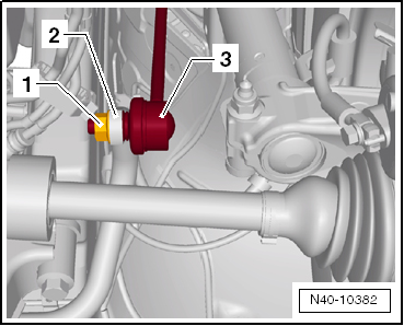
- Remove the hex nut -1- from the right and left coupling rod -3-.
- Remove the coupling rod -3- from the stabilizer bar -2- on the left and right sides.
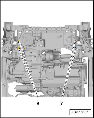
- Remove the stabilizer bar bolts -7 and 8-.
Leave the stabilizer bar in the installed position on the vehicle.
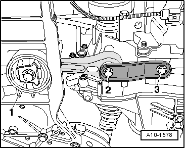
- Remove the bolt -1-.
- Remove the bolts -2 and 3-.
- Remove the pendulum support.
Pressing Out the Bonded Rubber Bushing
- Install the Rubber Bushing Assembly Device Kit -VAS6779A- on the subframe as shown.
- Position the Rubber Bushing Assembly Device Kit - Thrust Piece -VAS6779/1--1- with the flat side -arrow- on the bonded rubber bushing in the direction of travel.
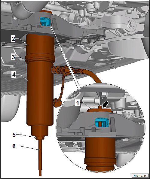
- Rubber Bushing Assembly Device Kit - Thrust Piece -VAS6779/1-
- Hydraulic Press - Bushing Tool Kit -Tube -VAS6779/4-, with the small outer diameter to the sub frame.
- Rubber Bushing Assembly Device Kit -Thrust Piece -VAS6779/5-
- Hydraulic Press -VAS6178- with Bearing Installer - Wheel Hub/Bearing Kit - Pressure Head -T10205/13-
- Rubber Bushing Assembly Device Kit - Hexagon Nut -VAS6779/3-
- Rubber Bushing Assembly Device Kit - Threaded Rod -VAS6779/2-
- Press out both bonded rubber bushings until the upper bonded rubber bushing -2- is visible in the pendulum support opening -arrow- in the subframe.
- Perform a visual inspection of the upper bonded rubber bushing outer race -2-.
If the upper bonded rubber bushing outer race -2- is deformed, it must be destroyed through the opening for the pendulum support -arrow- in the subframe.
- Using a chisel or similar tool -1-, make a break in the upper bonded rubber bushing outer race -2-.
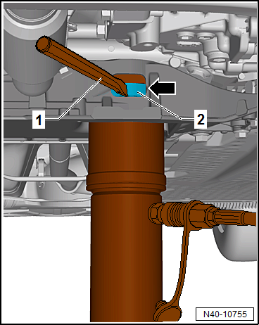
Note
This work sequence is necessary to prevent tilting of the bonded rubber bushing outer race in the area of the pendulum support opening in the subframe.
- Completely press out both bonded rubber bushings at the same time.
Preparing Bonded Rubber Bushings Before Pressing In
Note
- There are two different versions of the pendulum support bonded rubber bushing: the T version -I- and the V version -II-.
- Refer to the Parts Catalog for the allocation.
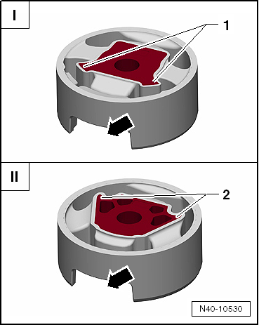
- The corners on the inner core -1- face toward the opening for the pendulum support -arrow- (T version).
- The corners on the inner core -2- face away from the opening for the pendulum support -arrow- (V version).
- Place the bonded rubber bushings -1 and 2- on top of each other so the openings -arrows- lay directly over each other.
- Tighten the bonded rubber bushings -1 and 2- using the original bolt -3- hand tight.
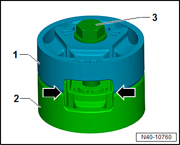
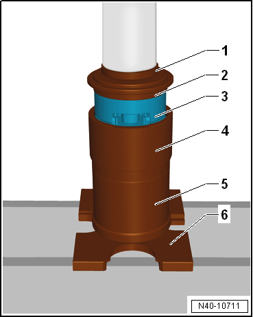
- Place the bonded rubber bushing -1- with the bolt head facing up in the larger diameter of the Rubber Bushing Assembly Device Kit - Funnel -VAS6779/6--2-.
- Align the bonded rubber bushing -1- in the Rubber Bushing Assembly Device Kit - Funnel -VAS6779/6--2-. The opening in the bonded rubber bushing must directly face the recess -arrows- in the Rubber Bushing Assembly Device Kit - Funnel -VAS6779/6--2-.
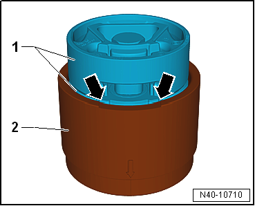
- Press the bonded rubber bushing -3- in the Rubber Bushing Assembly Device Kit - Funnel -VAS6779/6- until it stops as shown in the illustration.
- Press Piece - Multiple Use -VW412-
- Rubber Bushing Assembly Device Kit -Thrust Piece -VAS6779/5-, the side with the letter "A" points up
- Bonded rubber bushing
- Rubber Bushing Assembly Device Kit - Funnel -VAS6779/6-
- Rubber Bushing Assembly Device Kit - Tube -VAS6779/4-
- Press Plate -VW401-
- Remove the bolt from the bonded rubber bushing.
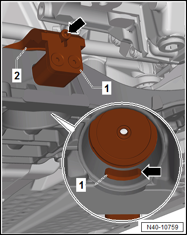
- Place the Hydraulic Press - Bushing Tool Kit-Counter Hold -VAS6779/7--1- front left in the direction of -arrow- on the subframe -2-.

- Insert the Rubber Bushing Assembly Device Kit - Insert -VAS6779/7-1A--1- in the pendulum support opening in the subframe.
- Attach the Rubber Bushing Assembly Device Kit - Insert -VAS6779/7-1A- with the bolt -arrow- on the Hydraulic Press - Bushing Tool Kit-Counter Hold -VAS6779/7--2-.
- Pay attention that the Rubber Bushing Assembly Device Kit - Counterhold -VAS6779/7-1A--1- is seated correctly in the subframe opening -arrow-.
Installing the Bonded Rubber Bushings
- Install the Rubber Bushing Assembly Device Kit -Threaded Rod -VAS6779/2--7- in the Rubber Bushing Assembly Device Kit - Counterhold -VAS6779/7--1-.
- Install the Rubber Bushing Assembly Device Kit -VAS6779- as shown in the illustration on the subframe.
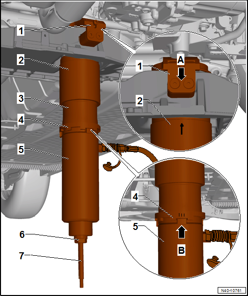
- Rubber Bushing Assembly Device Kit - Counterhold -VAS6779/7-
- Hydraulic Press - Bushing Tool Kit - Funnel -VAS6779/6-, -arrow marking- on the Funnel must be opposite of both bolts -arrow A-.
- Rubber Bushing Assembly Device Kit - Thrust Piece -VAS6779/9-
- Hydraulic Press - Bushing Tool Kit -Incremental Ring -VAS6779/8-, the marking -III- on the Incremental Ring must point to the cam -arrow B- on the Hydraulic Press - Bushing Tool Kit -Thrust Piece -VAS6779/9-.
- Hydraulic Press -VAS6178- with Bearing Installer - Wheel Hub/Bearing Kit Pressure Head -T10205/13-
- Hydraulic Press - Bushing Tool Kit - Hexagon Nut -VAS6779/3-
- Hydraulic Press - Bushing Tool Kit - Threaded Rod -VAS6779/2-
- Press in both bonded rubber bushings at the same time.
- Remove the Rubber Bushing Assembly Device Kit -VAS6779- from the subframe and check the position of the pressed in bonded rubber bushing.
- Fasten the stabilizer bar with the subframe and the coupling rod.
- Insert the pendulum support.
- Install the bolts -2 and 3- and tighten.
- Install the bolt -1- and tighten.
- Install the front noise insulation.

Tightening Specifications
| Bolt | Tightening Specification |
Pendulum support to the
transmission M10 x 35
|
50 Nm + 90º |
Pendulum support to the
transmission M10 x 75
|
50 Nm + 90º |
Pendulum support to the
transmission M12 x 1.5 x 50
|
60 Nm + 90º |
Pendulum support to the
transmission M12 x 1.5 x 85
|
60 Nm + 90º additional turn |
Pendulum support to the
subframe M14 x 1.5 x 70
|
100 Nm + 90º |
Stabilizer bar to
coupling rod
|
65 Nm |
Stabilizer bar to subframe
|
20 Nm + 90º |
 Subframe with Steering Gear, Removing and Installing
Special tools and workshop equipment required
Puller - Ball Joint -3287A-
Torque Wrench 1332 40-200Nm -VAG1332-
Removing
Turn the steering wheel in the straight position and remove the ignition ...
 Ball Joint, Checking
Axial Play, Checking
Forcefully pull control arm down in the direction of
-arrow- and press it up again.
Radial Clearance, Checking
Forcefully push the lower part of wheel inward and outward in ...
See More:
Volkswagen Tiguan Service and Repair Manual > Wheels, Tires, Wheel Alignment: Wheel/Tire Vibration, Causes and Solution
Vibration Causes
There are many causes for vibration. Vibration can also be caused by tire
wear, among other things. Tire wear caused by driving does not always develop
evenly over the entire tread. Due to this, a slight imbalance develops which
disturbs the smoothness of the formerly accurately ...
Volkswagen Tiguan Owners Manual
Volkswagen Tiguan Service and Repair Manual
- Body exterior
- Body Interior
- General Paint Information
- Paint
- Brake System
- Suspension, Wheels, Steering
- Wheel and Tire Guide
- Towing Guide
- Wheel and Tire Guide General Information
- Communication
- Electrical Equipment General Information
- Electrical Equipment from 06/2011
- Heating, Ventilation and Air Conditioning
- Refrigerant R134a Servicing
- 6-Speed Manual Transmission 02Q, OBB, and OFB
