Volkswagen Tiguan Service and Repair Manual: Subframe with Steering Gear, Removing and Installing
Special tools and workshop equipment required
- Puller - Ball Joint -3287A-
- Torque Wrench 1332 40-200Nm -VAG1332-
Removing
- Turn the steering wheel in the straight position and remove the ignition key so that the steering wheel lock engages.
Vehicles with "Keyless Access" Keyless Locking and Starting System
- Switch the ignition off and open the driver door so the steering wheel lock engages.
Continuation for All Vehicles
- Remove battery and the battery tray.
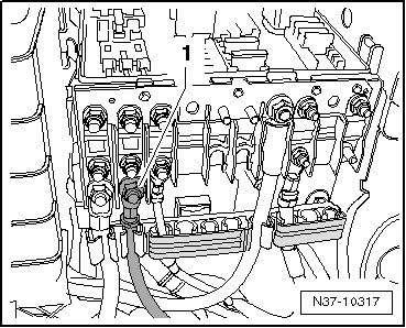
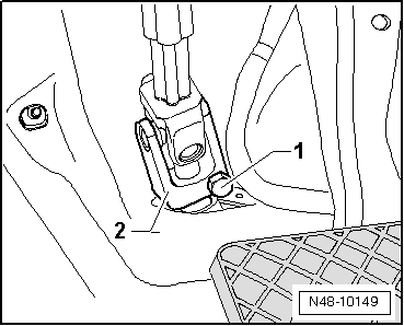
- Disconnect the cable -1- from the E-box.
- Disconnect the ground wire -2-.
- Disconnect the connector -3-.
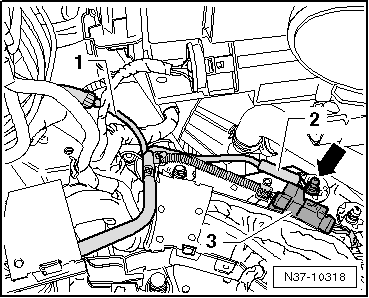
- Guide the wiring harness out of all the brackets on the longitudinal so it can be removed together with the steering gear.
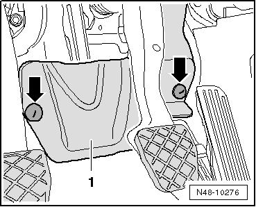
- Remove the nuts -arrows- and the footwell trim panel.
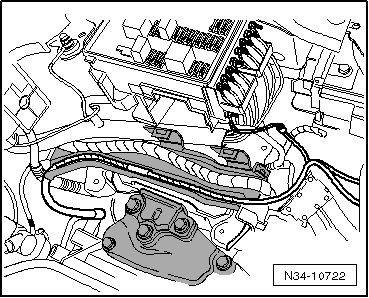
- Remove the bolt -1- and remove the universal joint -2- from the steering gear.
Caution
If the universal joint is separated from the steering gear, the following work cannot be performed:
- Connect the battery.
- Switching on the ignition
- Turning the steering gear
- Turning the steering column.
These points must be observed since performing these actions could cause irreparable damage.
- Remove the front wheels.
- Remove the lower noise insulation.
- Disconnect the connector for the service interval extension to the oil pan.
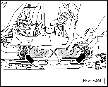
- Remove the exhaust system bracket from the subframe -arrows-.
- Remove coupling rods from stabilizer.
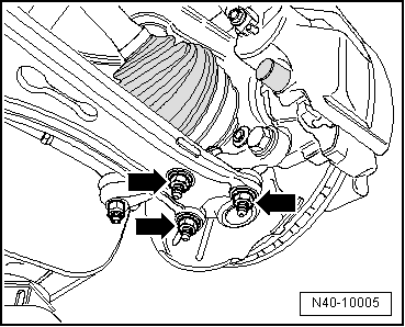
- Remove the nuts -arrows-.
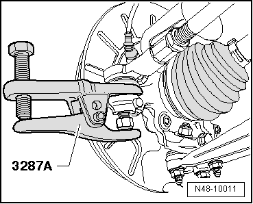
- Loosen the nut of the tie rod end, but do not remove yet.
To protect the thread, screw the nut on the pin a few turns.
- Press off tie rod end from wheel bearing housing with Puller - Ball Joint -3287A- and then remove nut.
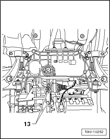
- Remove the bolts -13- and then remove the pendulum support from the transmission.
- Secure the subframe.
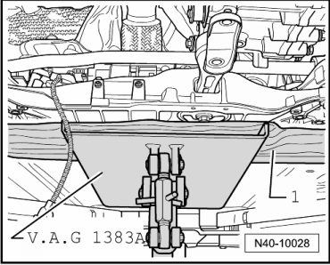
- Place the Engine/Gearbox Jack -VAG1383A- under the subframe.
- Place a block of wood -1-, for example, between Engine/Gearbox Jack -VAG1383A- and the subframe.
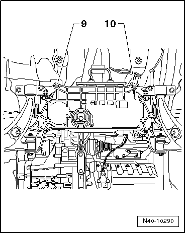
- Remove the bolts -9 and 10- and slightly lower the subframe. Observe electrical wires when doing this.
- Lower the Engine/Gearbox Jack -VAG1383A- and guide the steering gear wiring harness back.
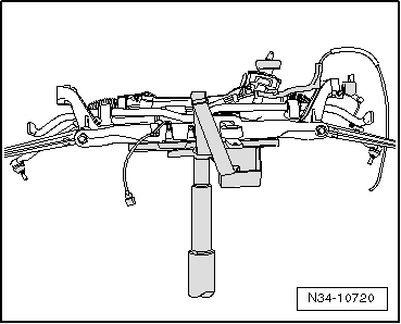
- Secure the subframe on the Engine and Gearbox Jack -VAS6931- with the accompanying strap.
Installing
Install in reverse order of removal.
- Install the battery tray and the battery.
- Install and tighten the noise insulation.
If the steering wheel is still crooked after using the Locating Pins -T10096- then an axle alignment is necessary. In this case the record it in the vehicles axle alignment log.
Tightening Specifications
| Component | Tightening Specification |
Mounting bracket to body
|
70 Nm + 180º |
Stabilizer bar to
subframe
|
20 Nm + 90º |
Stabilizer bar to
coupling rod
|
65 Nm |
Tie rod end to wheel
bearing housing
|
50 Nm |
Ball joint to aluminum
control arm:
|
60 Nm |
Ball joint to sheet steel
control arm
|
100 Nm |
Universal joint to
steering gear
|
30 Nm |
| Exhaust system bracket to subframe. | |
Tightening Specifications, Subframe to Body
| Bolt | Tightening Specification |
M12 x 1.5 x 90
|
70 Nm + 180º |
M12 x 1.5 x 100
|
70 Nm + 180º |
M12 x 1.5 x 110
|
70 Nm + 90º |
Tightening Specifications, Pendulum Support to the Transmission
| Bolt | Tightening Specification |
M10 x 35
|
50 Nm + 90º |
M10 x 75
|
50 Nm + 90º |
M12 x 1.5 x 85
|
60 Nm + 90º |
 Subframe without Steering Gear, Removing and Installing
Special tools and workshop equipment required
Torque Wrench 1331 5-50Nm -VAG1331-
Torque Wrench 1332 40-200Nm -VAG1332-
Removing
Note
Subframe is removed together with control arms.
Remove the l ...
 Subframe, Servicing
Special tools and workshop equipment required
Bearing Installer - Wheel Hub/Bearing Kit -T10205-
Torque Wrench 1332 40-200Nm -VAG1332-
Hydraulic Press -VAS6178-
Pneumatic/Hydraulic Foot Pump -VAS ...
See More:
Volkswagen Tiguan Service and Repair Manual > Front doors, Central locking system: Central Locking
Component Location Overview - Central Locking Components
Comfort System Central Control Module -J393-
Installed location: under the instrument panel on the front passenger
side
Removing.
Connector Station
Component location: right A-pillar.
Loosen the boot on the pillar to disconn ...
Volkswagen Tiguan Owners Manual
Volkswagen Tiguan Service and Repair Manual
- Body exterior
- Body Interior
- General Paint Information
- Paint
- Brake System
- Suspension, Wheels, Steering
- Wheel and Tire Guide
- Towing Guide
- Wheel and Tire Guide General Information
- Communication
- Electrical Equipment General Information
- Electrical Equipment from 06/2011
- Heating, Ventilation and Air Conditioning
- Refrigerant R134a Servicing
- 6-Speed Manual Transmission 02Q, OBB, and OFB
