Volkswagen Tiguan Service and Repair Manual: Clutch Mechanism
Component Location Overview - Clutch Mechanism
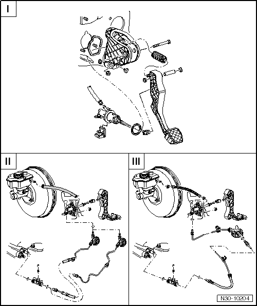
- Chapter "Overview - Pedal Assembly, Scirocco, CC, Golf Cabriolet, Passat
and Tiguan"
Chapter "Overview - Pedal Assembly, Golf, Golf Wagon" - Chapter "Overview - Clutch Hydraulics, Scirocco, CC, Golf Cabriolet,
Passat and Tiguan"
Chapter "Overview - Clutch Hydraulics, Golf, Golf Wagon" - Chapter "Overview - Clutch Hydraulics, Scirocco, CC, Golf Cabriolet,
Passat and Tiguan, RHD Vehicle"
Chapter "Overview - Clutch Hydraulics, Golf, Golf Wagon, RHD Vehicle"
Overview - Pedal Assembly
Overview - Pedal Assembly, Scirocco, CC, Golf Cabriolet, Passat and Tiguan
Note
- Lubricate all bearing areas and contact surfaces.
- Grease allocation. Refer to the Parts Catalog.
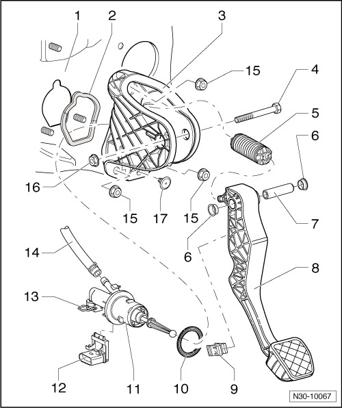
- Bulkhead
- With a mount for the mounting bracket
- Seal
- Self-adhesive
- Replace after removing the mounting bracket
- Attached to the mounting bracket
- Mounting Bracket
- For the clutch pedal mount
- Some equipment versions have a damper.
- Removing and installing.
- Bolt
- Over-Center Spring
- Lubricate all bearing areas and contact surfaces.
- Grease allocation. Refer to the Parts Catalog.
- Removing and installing.
- Bearing Bushing
- Mounting Pin
- Lubricate all bearing areas and contact surfaces.
- Grease allocation. Refer to the Parts Catalog.
- Clutch Pedal
- Lubricate all bearing areas and contact surfaces.
- Grease allocation. Refer to the Parts Catalog.
- Removing and installing.
- Base Plate
- Lubricate all bearing areas and contact surfaces.
- Grease allocation. Refer to the Parts Catalog.
- To remove and install, disconnect the clutch master cylinder from the clutch pedal.
- Seal
- Replace after removing
- Between the clutch master cylinder and the mounting bracket
- Clutch Master Cylinder
- Removing and installing.
- Clutch Position Sensor -G476-
- Can be checked in Guided Fault Finding. Refer to Vehicle Diagnostic Tester.
- Allocation. Refer to the Parts Catalog.
- Removing and installing.
- Clamp
- The clamp must be removed in order to remove/install the hose/line assembly
- Hose
- Made of plastic.
- Nut
- 25 Nm
- Replace after removing
- For the mounting bracket to the bulkhead
- Quantity: 3
- Self-locking
- Nut
- 25 Nm
- Replace after removing
- Self-locking
- Stop
- For the clutch pedal
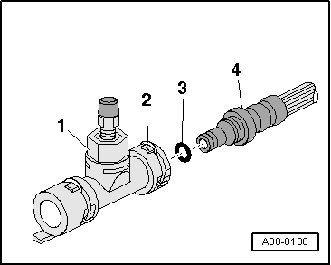
Plastic Hose -1-
- The seals -2- must be inside the hose.
- Replace with the hose if damaged
Mounting Bracket with Damper -arrow-
Overview - Clutch Hydraulics
Overview - Clutch Hydraulics, Scirocco, CC, Golf Cabriolet, Passat and Tiguan
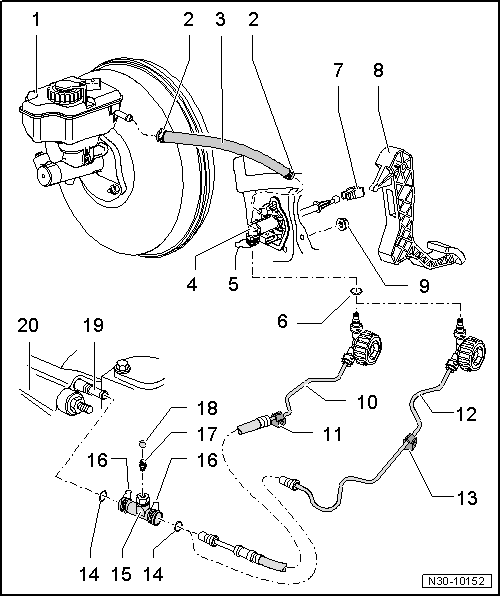
- Brake Fluid Reservoir
- Spring Clamp
- Not on all vehicles
- Hose
- Rubber
- Made of plastic.
- Clutch Master Cylinder
- Removing and installing.
- Clamp
- To remove and install the hose/line assembly or pipe, pull the clamp all the way out.
- On some clutch master cylinders, it is pulled out on the side
- Seal/O-Ring
- Replace if damaged
- Install on the line connection
- Install with brake fluid
- Seals/O-rings suitable for the line connection material.
- Allocation. Refer to the Parts Catalog.
- Base Plate
- To remove and install, disconnect the clutch master cylinder from the clutch pedal.
- Clutch Pedal
- Removing and installing.
- Nut
- Tightening specification.
- Hose/Line Assembly
- Allocation. Refer to the Parts Catalog.
- To remove, remove the battery and battery tray.
- Removing and installing.
- Bracket
- For hose/line assembly
- Attached to the body
- Covered by the assembly mounting
- Bracket differentiation.
- Line
- Allocation. Refer to the Parts Catalog.
- To remove, remove the battery and battery tray.
- Removing and installing.
- Bracket
- For the pipe line
- Attached to the body
- Covered by the assembly mounting
- Bracket differentiation.
- Seal/O-Ring
- Replace if damaged
- Install on the line connection
- Install with brake fluid
- Seals/O-rings suitable for the line connection material.
- Allocation. Refer to the Parts Catalog.
- Bleeder
- Removing and installing.
- Clamp
- The clamp must be removed in order to remove/install the hose/line assembly
- Breather Valve
- Bleed clutch mechanism.
- With hex fitting - tightening specification: 4.5 Nm
- Flat on both sides: seal off to stop.
- Dust Cap
- Clutch Slave Cylinder
- Removing and installing.
- Transmission
Bracket Differentiation
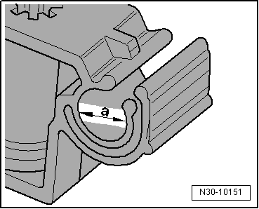
| Dimension "a" mm | Line Version |
| 8 | Line |
| 6 | Hose/Line Assembly |
Overview - Clutch Release Mechanism
- Clutch Slave Cylinder with Release Bearing
- Must be replaced together because they are a single unit
- Do not wash the bearing, just wipe it off.
- Replace a loud bearing together with the clutch slave cylinder
- Removing and installing.For release bearing with additional plastic washer.
- Allocation. Refer to the Parts Catalog.
- Bolt
- 12 Nm for metal clutch slave cylinder (without locking fluid)
- 15 Nm for plastic clutch slave cylinder (with locking fluid)
- Replace after removing
- Pay attention to the thread pitch on the bolt when cleaning the threaded hole in the clutch housing.
- Carefully tighten diagonally and in step so that the tabs on the clutch slave cylinder do not break
- Quantity: 3
- Clamp
- To remove and install the line, remove the clip up to the stop
- Install until the clip engages audibly
- Line
- To the clutch master cylinder
- O-Ring
- Replace if damaged
- Install on the line connection
- Install with brake fluid
- Allocation. Refer to the Parts Catalog.
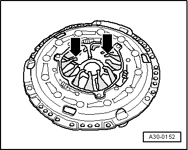
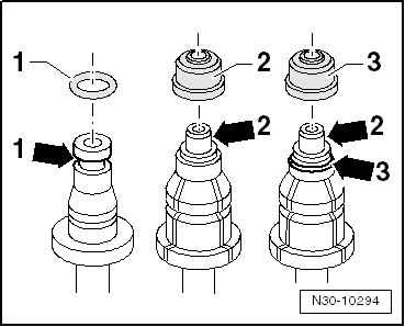
Release Bearing with Additional Plastic Washer
Identified by: tabs -arrow- on the plastic washer.
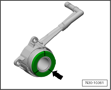
Only for Release Bearing with Additional Plastic Washer: Pressure Plate Diaphragm Spring (-arrows-) with a Slightly Lower Installation Height.
- Install the release bearing with additional plastic washer and the pressure plate diaphragm spring with a slightly lower installation height.
Clutch Master and Clutch Slave Cylinder, Checking
Before replacing the clutch master cylinder due to an assumed defect, perform the Guided Fault Finding first. Refer to Vehicle Diagnostic Tester.
Clutch Position Sensor -G476-, Removing and Installing- Chapter "Clutch Position Sensor -G476-, Removing and Installing, Scirocco, CC, Golf Cabriolet and Passat"
- Chapter "Clutch Position Sensor -G476-, Removing and Installing, Tiguan"
- Chapter "Clutch Position Sensor -G476-, Removing and Installing, Golf, Golf Wagon"
- Chapter "Over-Center Spring, Removing and Installing, CC, Passat"
- Chapter "Over-Center Spring, Removing and Installing, Tiguan"
- Chapter "Over-Center Spring, Removing and Installing, Golf and Golf Wagon"
Clutch Pedal, Removing and Installing
- Chapter "Clutch Pedal, Removing and Installing, CC, Passat"
- Chapter "Clutch Pedal, Removing and Installing, Tiguan"
- Chapter "Clutch Pedal, Removing and Installing, Golf, Golf Wagon"
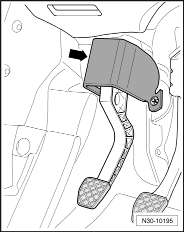
Mounting Bracket, Removing and Installing
- Chapter "Mounting Bracket, Removing and Installing, Scirocco and Golf Cabriolet"
- Chapter "Mounting Bracket, Removing and Installing, CC, Passat"
- Chapter "Mounting Bracket, Removing and Installing, Golf, Golf Wagon"
- Chapter "Mounting Bracket, Removing and Installing, Tiguan"
Clutch Master Cylinder, Removing and Installing
Clutch Master Cylinder, Removing and Installing, Scirocco, CC, Golf Cabriolet, Passat and Tiguan
Special tools and workshop equipment required
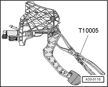
- Clutch Pedal Pliers -T10005-
Removing
Note
- Before replacing the clutch master cylinder due to a suspected defect, perform the Guided Fault Finding first. Refer to Vehicle Diagnostic Tester.
- When working inside the footwell, cover the carpet with cloths to protect it from leaking brake fluid.
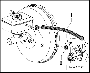
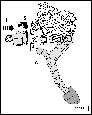
- Remove the mounting bracket.
- Release the mount for the clutch master cylinder actuator rod using the Clutch Pedal Pliers -T10005-.
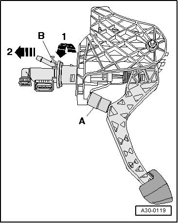
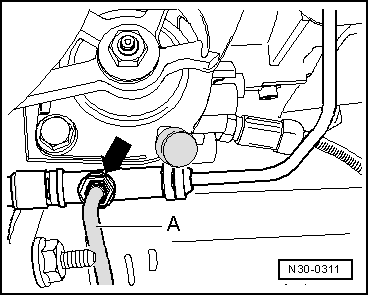
- Place a spacer -A- between the clutch pedal and the stop and push the clutch pedal down as far as the spacer.
Spacer length = approximately 40 mm (for example, 1/2 socket insert)
- Unlock the securing clip -B- and remove the clutch master cylinder from the mounting bracket -arrow 1- and in direction of -arrow 2-.
Installing
Move the clutch pedal into its rest position.
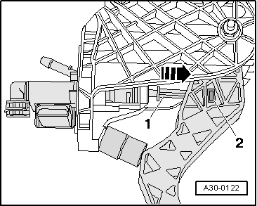
- Attach the mount -2- to the clutch master cylinder actuator rod -1-.
- Place a spacer -A- between the clutch pedal and the stop and push the clutch pedal down as far as the spacer.
Spacer length = approximately 40 mm (for example, 1/2 socket insert)
- Lock the clutch master cylinder to the mounting bracket in direction of -arrow 1 and arrow 2-.
- Push the clutch master cylinder actuator rod -1- in direction of -arrow- until the mount -2- audibly engages inside the clutch pedal.
- Install the mounting bracket.
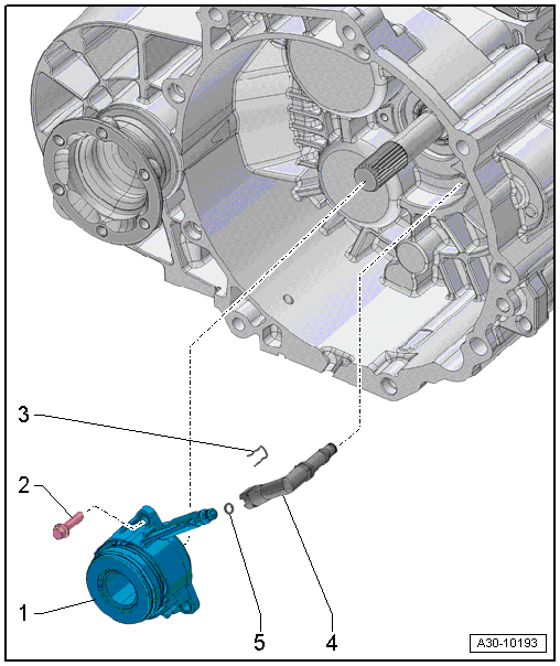
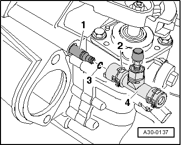
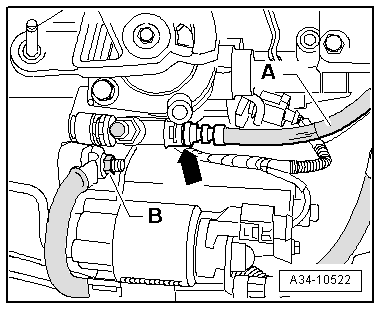
Bleeder, Removing and Installing
Hose/Line Assembly or Pipe -4- on Bleeder -1-, Removing and Installing
- To remove, open the clip -2- with a screwdriver or a pointed tool and pull off hose/line assembly or pipe -4- at bleeder -1-.
- To install, press hose/line assembly or pipe with new O-ring -3- onto the bleeder connection, until clip audibly engages.
- Pull on the line to make sure it is secure.
Removing and Installing the Bleeder -4- from the Clutch Slave Cylinder
- To remove, open the clip -2- with a screwdriver or a pointed tool and remove bleeder -4- from clutch slave cylinder -1-.
- To install, check the O-ring -3- on the clutch slave cylinder. Press in the bleeder at the clutch slave cylinder connector until the clip -2- engages audibly.
- To check, pull on the bleeder.
Disconnect and Connect Clutch Mechanism Wires
Separating
- Open the clip -3- with a screwdriver and remove the hose/line assembly -1- from the connection -4-.
Connecting
Note
- An O-ring can also be installed instead of a seal -2-.
- Replace the damaged seal -2-.
- Press in the hose/line assembly -1- at the connection -4- until the clip -3- engages audibly.
- Pull on the hose/line assembly to make sure it is secure.
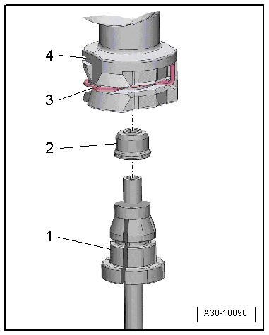
Sealing Rings/O-Rings for Hose/Line Assembly or Pipe
| Item | Line Connection Version |
| 1 | Line connection with a groove all the way around -arrow 1- |
| 2 | Line connection with a shoulder -arrow 2- |
| 3 | Line connection with a shoulder -arrow 2- and with a groove all the way around -arrow 3- |
The seal / O-ring must be installed in the groove -arrow 1- and -arrow 3-.
- Bleed the clutch mechanism.
Special tools and workshop equipment required
- Hose Clamps - Up To 25 mm -3094-
Removing
- Disconnect the battery.
- Remove the air filter housing if the lines are not accessible.
Continuation for All
- Remove the battery and the battery tray.
Caution
Danger of leaking brake fluid.
- Be careful not to get any brake fluid on the longitudinal member or on the transmission when performing the following work. If it does, clean the area thoroughly.
- Place a lint-free cloth under the clutch master cylinder.
Clamp off the hose -2- to the clutch master cylinder using Hose Clamps - Up To 25mm -3094-.

Note
- A slight deformation of the hose remains after the Hose Clamps - Up To 25mm -3094- have been removed.
- The hose is not faulty.
- After removing the Hose Clamps - Up To 25mm -3094-, the hose must be formed back into its original shape.
- Remove clip for hose/line assembly -1- all the way and remove hose/line assembly.
- Seal off openings.
- Remove the clip -arrow- all the way and then remove the hose/line assembly -A- from the bleeder.
Ignore -B-.
- Seal the open lines and connections with clean plugs if necessary from the Engine Bung Set -VAS6122-.
- Free up the hose/line assembly and remove it.
Installing
Install in the reverse order of removal while noting the following:
- Connect hose/line assembly -1- with clutch master cylinder.
- Pull on the line to make sure it is secure.

- Push the hose/line assembly -4- with the O-ring -3- onto the bleeder connection -1- until the clip -2- audibly locks into place.
- Pull on the line to make sure it is secure.
After removing the Hose Clamp up to 25 mm -3094-, the return hose -2- (⇒ previous illustration) must be formed back into its original shape.

- Bleed the clutch mechanism.
- Install the air filter housing.
Continuation for All
- Install the battery tray, battery and the battery cover.
Clutch Slave Cylinder with Release Bearing, Removing and Installing
Special tools and workshop equipment required
- Torque Wrench 1331 5-50Nm -VAG1331-
Note
- The clutch slave cylinder and the release bearing are a single unit and are replaced together.
- Pay attention to the thread pitch on the bolts when cleaning the threaded hole in the clutch housing.
Removing
Transmission is removed.
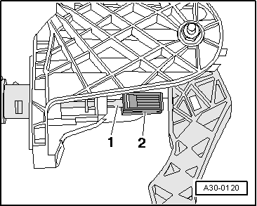
- Open the clip -2- with a screwdriver or a pointed tool and remove bleeder -4- from clutch slave cylinder -1-.
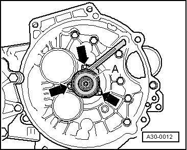
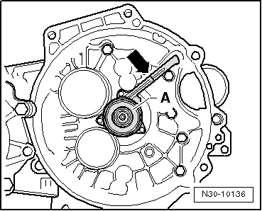
- Remove the bolts -arrows-.

- Remove the clutch slave cylinder together with the release bearing -A-.
Installing
Install in the reverse order of removal while noting the following:
- Tighten the slave cylinder bolts in small increments only.
Otherwise, there is the danger that the tabs with the fastening holes could break off.
- Check the O-ring -3- on the clutch slave cylinder for damage.
- Push the bleeder -4- onto the clutch slave cylinder connection -1- until the clip -2- clicks into place.
- To check, pull on the bleeder.
- Install the transmission.
- Bleed the clutch mechanism.

Tightening Specifications
- Clutch slave cylinder with release bearing to transmission.
Clutch Mechanism, Bleeding
Special tools and workshop equipment required
- Brake Charger/Bleeder Unit -VAS5234-
Note
- Bleed the system after working on the hydraulic clutch mechanism.
- Make sure no brake fluid gets on the transmission when performing the following work.
- It is not necessary to pre-fill the system.
- Fill the brake fluid reservoir up to the "Max" marking with brake fluid before bleeding.
- The clutch pedal is in the neutral position and is not pressed.
- Brake fluid allocation. Refer to the Parts Catalog.
- Remove the air filter housing if it makes the bleeder inaccessible.
Continuation for All
- Return clutch pedal to the rest position.
- Remove cap from the breather valve -arrow-.
- Connect the Brake Charger/Bleeder Unit -VAS5234-.
If necessary use the Bleeder Hose (670 mm) -VAG1238/B3-.
- Connect the bleed hose -A- with the collector bottle pressure hose.
- Switch the Brake Charger/Bleeder Unit -VAS5234- on.
Working pressure 2.0 bar (29 psi).
- Open the breather valve approximately 1/4 turn.
- Move the clutch pedal manually 15 to 20 time very quickly from stop to stop.
- Close the breather valve and switch the Brake Charger/Bleeder Unit -VAS5234- off.
- Breather valve with hex fitting: Tightening specification, 4.5 Nm
- Breather valve flattened on both sides: seal off all the way
- After completing the bleeding procedure, and the pressure has dropped from 2 bar (29 psi), operate the clutch pedal an additional 10 times by foot.
- Install the air filter housing.
Clutch Release Mechanism, Servicing
Special tools and workshop equipment required
- Torque Wrench 1331 5-50Nm -VAG1331-
- Grease for Clutch Disc Shaft Splines
- Grease allocation. Refer to the Parts Catalog.
The transmission is removed.
- Remove and attach the clutch slave cylinder with the release bearing -arrows-.

Clutch Slave Cylinder -A- with Divided Supply Line
The supply line is divided in area with -arrows- on some clutch slave cylinders
Allocation. Refer to the Parts Catalog.
Release Bearing with Additional Plastic Washer
Identified by: tabs -arrow- on the plastic washer.

Only for Release Bearing with Additional Plastic Washer: Pressure Plate Diaphragm Spring (-arrows-) with a Slightly Lower Installation Height.
- Install the release bearing with additional plastic washer and the pressure plate diaphragm spring with a slightly lower installation height.

Allocation. Refer to the Parts Catalog.
- Install the transmission.
- Bleed the clutch mechanism.
Tightening Specifications
- Clutch slave cylinder with release bearing to transmission.
 Clutch
...
 Clutch Manufacturers, Differentiating
Clutch Manufacturers, Differentiating
Only Vehicles with 2.0L Turbo Diesel Engine
Either a "Sachs" or a "LuK" clutch may be installed.
It is possible to tell which clutch the vehicle has with the tran ...
See More:
Volkswagen Tiguan Owners Manual > Vehicle key set: Indicator light in the remote control vehicle key
Fig. 20 Indicator light in the remote
control vehicle key.
Read and follow the introductory information and
safety information first⇒Introduction
to the subject If a button in the remote control vehicle key is pressed briefly,
the indicator light (arrow) ⇒ Fig. 20 will flash once b ...
Volkswagen Tiguan Owners Manual
Volkswagen Tiguan Service and Repair Manual
- Body exterior
- Body Interior
- General Paint Information
- Paint
- Brake System
- Suspension, Wheels, Steering
- Wheel and Tire Guide
- Towing Guide
- Wheel and Tire Guide General Information
- Communication
- Electrical Equipment General Information
- Electrical Equipment from 06/2011
- Heating, Ventilation and Air Conditioning
- Refrigerant R134a Servicing
- 6-Speed Manual Transmission 02Q, OBB, and OFB
