Volkswagen Tiguan Service and Repair Manual: Flushing Circuit Block Diagrams
Note
- The arrows in the following illustrations show the direction of refrigerant flow while flushing. During flushing, refrigerant flows in the opposite direction than during A/C system operation, therefore the high pressure side of A/C service station is connected to A/C compressor at low pressure side of refrigerant circuit.
- These block diagrams indicate a refrigerant circuit with restrictor and reservoir and a refrigerant circuit with expansion valve, receiver/dryer and a second evaporator (optional equipment on certain vehicles)
- Depending on the design of the A/C service station, check valves can be installed between the refrigerant circuit and the A/C service station. They guarantee the correct direction of refrigerant flow during flushing.
Refrigerant Circuit with Restrictor and Reservoir
Note
On vehicles with restrictor and reservoir, the restrictor and reservoir are removed. Restrictor refrigerant pipes are reassembled. The refrigerant pipe to the removed reservoir are connected with each other via two adapters and the Refrigerant Circuits Adapter Set 2 - Adapter 31 -VAS6338/31- (from the Refrigerant Circuits Adapter Set 1 -VAS6338/1-).
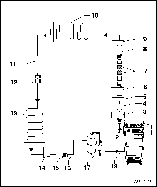
- A/C service station
- With electronics and a flushing program, for example A/C Service Station with Flushing Device -VAS6380- or Air Conditioning Flush Tool -VAS6337-.
- If an A/C service station without a flushing program is used, the procedure must be performed manually (evacuate, flush 3 times with at least 4 kg refrigerant each and extract refrigerant again, evacuate).
- A/C service station refrigerant hose
- From high pressure side of A/C service station (mostly colored red) to low pressure side connection of A/C compressor on refrigerant circuit (larger diameter).
- Adapter for connecting low pressure side to refrigerant circuit
- Different versions depending on vehicle.
- From the Refrigerant Circuits Adapter Set 1 -VAS6338/1-
- Low pressure side connection on refrigerant circuit
- Different versions depending on vehicle.
- On refrigerant line from A/C compressor to reservoir.
- Connection to reservoir
- Different versions depending on vehicle.
- On refrigerant line from A/C compressor to reservoir.
- Adapter for bridging the removed reservoir
- Different versions depending on vehicle.
- From the Refrigerant Circuits Adapter Set 1 -VAS6338/1-
- Refrigerant charge hose.
- For example Refrigerant Circuits Adapter Set 1 - Adapter 31 -VAS6338/31- (from the Refrigerant Circuits Adapter Set 1 -VAS6338/1-)
- Adapter for bridging the removed reservoir
- Different versions depending on vehicle.
- From the Refrigerant Circuits Adapter Set 1 -VAS6338/1-
- Connection to reservoir
- Different versions depending on vehicle.
- Evaporator
- Component location of restrictor
- Restrictor is removed.
- Remove restrictor. Refer to Heating, Ventilation & Air Conditioning.
- Bolts in refrigerant line
- Bolt together again after removing restrictor. Refer to Heating, Ventilation & Air Conditioning.
- Condenser
- High pressure side connection on refrigerant circuit
- Adapter to connection for high pressure side on refrigerant circuit
- Different versions depending on vehicle.
- From the Refrigerant Circuits Adapter Set 1 -VAS6338/1-
- Charge hose for refrigerant circuit flushing device
- From connection to the high pressure side of the A/C compressor on the refrigerant circuit (smaller diameter) to input of Refrigerant Circuit Flushing Device -VAS6336/1- or Air Conditioning Flush Tool -VAS6337/1A-.
- Flushing equipment for refrigerant circuits
- Different versions and different construction, for example Refrigerant Circuit Flushing Device -VAS6336/1- or Air Conditioning Flush Tool -VAS6337/1-.
- With filter, viewing glass, security valve, heater, refrigerant container, etc. (depending on version).
- Depending on the construction of the A/C service station and of refrigerant circuit flushing device, a check-valve may be installed at output of refrigerant circuit flushing device (to guarantee correct direction of refrigerant flow during flushing).
- A/C service station refrigerant hose
- From the low pressure side of the service station (mostly blue) to the output of the flushing device for refrigerant circuits.
Refrigerant circuit with expansion valve, receiver/dryer and second evaporator
Note
- This block diagram shows a refrigerant circuit with expansion valve, receiver/dryer and second evaporator (optional equipment on certain vehicles).
- On vehicles with an expansion valve and receiver/dryer, the expansion valve is removed and replaced by an adapter. Depending on vehicle, receiver/dryer is flushed or dryer cartridge is removed. Depending on receiver/dryer version, it is to be removed and line connections to receiver/dryer are to be connected to each other with two adapters and a charging hose.
- On a vehicle with only one evaporator, the components as of position "16" are not installed or are not required.
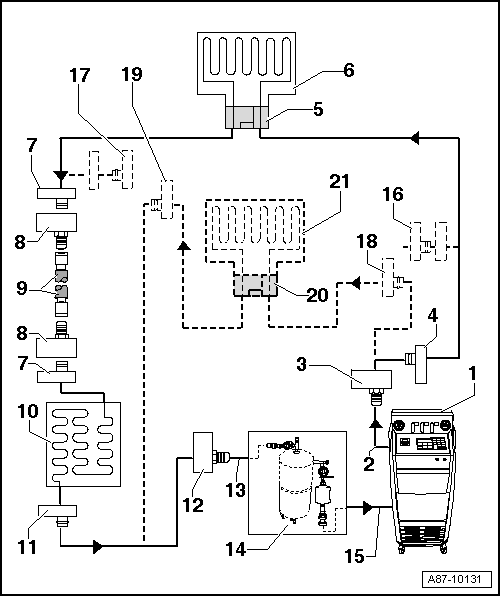
- A/C service station
- With electronics and a flushing program, for example A/C Service Station with Flushing Device -VAS6380- or Air Conditioning Flush Tool -VAS6337-.
- If an A/C service station without program is used for flushing, the procedure should be performed manually.
- Extract the refrigerant, if necessary.
- Set up the Refrigerant Circuit Flushing Device -VAS6336/1- or Air Conditioning Flush Tool -VAS6337/1A- between the A/C service station and refrigerant circuit return line.
- Evacuate refrigerant circuit for 20 minutes and then charge with 4 kg refrigerant R134a. Then extract again and repeat the procedure 2 more times. If the refrigerant in the viewing glass(es) is not clear after the third attempt, an additional attempt is necessary.
- A/C service station refrigerant hose
- From high pressure side of A/C service station (mostly colored red) to low pressure side connection of A/C compressor on refrigerant circuit (larger diameter).
- Adapter for connecting low pressure side to refrigerant circuit
- Different versions depending on vehicle.
- From the Refrigerant Circuits Adapter Set 1 -VAS6338/1-
- Low pressure side connection on refrigerant circuit
- Different versions depending on vehicle.
- Adapter for the removed expansion valve
- Different versions depending on vehicle.
- From the Refrigerant Circuits Adapter Set 1 -VAS6338/1-
- Evaporator
- Connection to receiver/dryer
- Different versions depending on vehicle.
- Not present on vehicles with a dryer cartridge in receiver/dryer on condenser or a receiver/dryer installed in the condenser. Refer to Heating, Ventilation & Air Conditioning.
- Adapter for bridging the removed receiver/dryer
- Not required for all vehicles.
- Different versions depending on vehicle.
- From the Refrigerant Circuits Adapter Set 1 -VAS6338/1-
- Refrigerant charge hose.
- For example Refrigerant Circuits Adapter Set 1 - Adapter 31 -VAS6338/31- (from the Refrigerant Circuits Adapter Set 1 -VAS6338/1-)
- Condenser
- If a receiver/dryer with dryer cartridge is installed on the condenser, dryer cartridge must be removed (seal again the receiver/dryer on or in the condenser after removing). Refer to Heating, Ventilation & Air Conditioning.
- If receiver/dryer is built directly on the condenser, receiver/dryer is to be removed and replaced only after flushing. Refer to Heating, Ventilation & Air Conditioning.
- High pressure side connection on refrigerant circuit
- Different versions depending on vehicle.
- Adapter to connection for high pressure side on refrigerant circuit
- Different versions depending on vehicle.
- From the Refrigerant Circuits Adapter Set 1 -VAS6338/1-
- Charge hose for refrigerant circuit flushing device
- From connection to the high pressure side of the A/C compressor on the refrigerant circuit (smaller diameter) to input of refrigerant circuit flushing device.
- Flushing equipment for refrigerant circuits
- Different versions and different construction, for example Refrigerant Circuit Flushing Device -VAS6336/1- or Air Conditioning Flush Tool -VAS6337/1-.
- With filter, viewing glass, security valve, heater, refrigerant container, etc. (depending on version).
- Depending on the construction of the A/C service station and of refrigerant circuit flushing device, a check-valve may be installed at output of refrigerant circuit flushing device (to guarantee correct direction of refrigerant flow during flushing).
- A/C service station refrigerant hose
- From the low pressure side of the service station (mostly blue) to the output of the flushing device for refrigerant circuits.
- Adapter to seal output to second evaporator
- Only required for certain vehicles with optional equipment "second evaporator".
- From the Refrigerant Circuits Adapter Set 2 -VAS6338/50-.
- Adapter to seal output to second evaporator
- Only required for certain vehicles with optional equipment "second evaporator".
- From the Refrigerant Circuits Adapter Set 2 -VAS6338/50-.
- Low pressure side connection on refrigerant circuit to second evaporator
- Different versions depending on vehicle.
- Only present on certain vehicles with optional equipment "second evaporator".
- Connection of high pressure side on refrigerant circuit to second
evaporator
- Different versions depending on vehicle.
- Only present on certain vehicles with optional equipment "second evaporator".
- Adapter for the removed expansion valve on second evaporator
- Different versions depending on vehicle.
- Only required for certain vehicles with optional equipment "second evaporator".
- From the Refrigerant Circuits Adapter Set 2 -VAS6338/50-.
- Second evaporator
- Only present on certain vehicles with optional equipment "second evaporator".
 General Information
Vehicles with a high voltage system (hybrid vehicles)
Observe all of the additional warnings for all work performed on vehicles
with the high voltage system.
WARNING
Risk of unintended engine start
T ...
 Electrically Driven A/C Compressor, Flushing
Vehicles with a high voltage system
Observe all of the additional warnings for all work performed on vehicles
with the high voltage system.
WARNING
Risk of unintended engine start
The ignition must b ...
See More:
Volkswagen Tiguan Service and Repair Manual > Top Coats: Two-Part HS Top Coat
Definition:
Two-Part HS Solid Top Coat -L2K 073 ... ..-
Two-Part HS Mixed Paint -L2K 074 ... ..-
Product Description
The two-part HS top coat series is a high solid top coat system. It is used
for vehicle painting.
The color program is extensively coordinated through an assortment of paint
mix ...
Volkswagen Tiguan Owners Manual
Volkswagen Tiguan Service and Repair Manual
- Body exterior
- Body Interior
- General Paint Information
- Paint
- Brake System
- Suspension, Wheels, Steering
- Wheel and Tire Guide
- Towing Guide
- Wheel and Tire Guide General Information
- Communication
- Electrical Equipment General Information
- Electrical Equipment from 06/2011
- Heating, Ventilation and Air Conditioning
- Refrigerant R134a Servicing
- 6-Speed Manual Transmission 02Q, OBB, and OFB
