Volkswagen Tiguan Service and Repair Manual: Steering Column Switch Mount
General Information
Removing and installing the steering column switch mount is different for the two manufacturers.
- Steering Column Switch Mount, Removing and Installing, Valeo.
- Steering Column Switch Mount, Removing and Installing, Kostal.
WARNING
Before working on electronic system and removing the steering wheel the following conditions must be met:
The technician must discharge static electricity. This is accomplished by touching grounded metal like, for example, water pipes, heating pipes, metal carriers or a heater pipe.
If this note is ignored it can result in failure of the control modules during later operation.
- Remove the battery ground cable.
- Wheels must be located in straight ahead position.
If this note is ignored, it can result in failure of the airbag system during later operation.
Caution
If the universal joint is separated from the steering gear, or the Steering Angle Sensor -G85- is removed, do not perform the following tasks:
- Connecting the battery
- Turning on the ignition
- Turning the steering gear.
- Turning the steering column.
These points must be followed otherwise, it can lead to irreparable damage.
Steering Column Switch Mount, Removing and Installing, Valeo
Special tools and workshop equipment required
- Torque Wrench 1410 -VAG1410-
- Angled Hand Drill
Caution
Always follow the sequence when removing and installing steering column switch components.
WARNING
Before working on electronic system and removing the steering wheel the following conditions must be met:
The technician must discharge static electricity. This is accomplished by touching grounded metal like, for example, water pipes, heating pipes, metal carriers or a heater pipe.
If this note is ignored it can result in failure of the control modules during later operation.
- Remove the battery ground cable.
- Wheels must be located in straight ahead position.
If this note is ignored, it can result in failure of the airbag system during later operation.
Caution
If the universal joint is separated from the steering gear, or the Steering Angle Sensor -G85- is removed, do not perform the following tasks:
- Connecting the battery
- Turning on the ignition
- Turning the steering gear.
- Turning the steering column.
These points must be followed otherwise, it can lead to irreparable damage.
Removing
Note
The shear bolts -1- on the Electronic Steering Column Lock Control Module -J764- must be drilled out in order to remove the steering column switch mount -2-. New shear bolts will be needed later for installing. Refer to the Parts Catalog.

Caution
- Before drilling out shear bolts, always ensure all components secured to mount are removed beforehand.
- By drilling out, drill shavings can reach the neighboring components, which can lead to damage and/or malfunctions!
- When removing the steering column switch components, observe the specified sequence.
Caution
Always follow the procedure as described in the Repair Manual when disconnecting and connecting the battery.
Removing
- Disconnect the battery.
- Remove the components on the mount in the specified sequence.
Once all components secured to the mount have been removed, the mount can be removed:
- Drill out the shear bolts -1- of the Electronic Steering Column Lock Control Module -J764--3-.
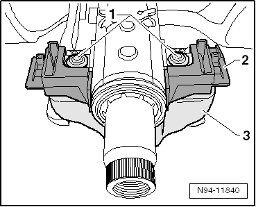
Note
M8 bolts -1-, hole diameter 6.8 mm.
- Disconnect the connector on the back of the Electronic Steering Column Lock Control Module -J764--3- and then remove the Electronic Steering Column Lock Control Module -J764-, together with the steering column switch mount -2-, from the steering column.
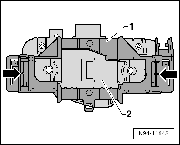
- Open the retainers -arrows- on the steering column switch mount and remove the mount -1- from the Electronic Steering Column Lock Control Module -J764--2-.
Installing
- Install the steering column switch mount -1- on the Electronic Steering Column Lock Control Module -J764--2- until it locks in place.
- Slide the Steering Column Combination Switch -E595- onto the steering column switch mount until it locks in place.
- Slide the pre-assembled unit of the Electronic Steering Column Lock Control Module -J764-, the steering column switch mount and the Steering Column Combination Switch -E595- straight onto the steering column all the way and align it with respect to the threaded holes.

- Attach the Electronic Steering Column Lock Control Module -J764- to the steering column with new shear bolts -1-.
- Tighten the new shear bolts -1- until the bolt heads shear off.
- Install all components accordingly in the reverse order.
Note
Code the new Electronic Steering Column Lock Control Module -J764- after installing.
Steering Column Switch Mount, Removing and Installing, Kostal
Special tools and workshop equipment required
- Torque Wrench 1410 -VAG1410-
- Angled Hand Drill
Caution
Always follow the sequence when removing and installing steering column switch components.
WARNING
Before working on electronic system and removing the steering wheel the following conditions must be met:
The technician must discharge static electricity. This is accomplished by touching grounded metal like, for example, water pipes, heating pipes, metal carriers or a heater pipe.
If this note is ignored it can result in failure of the control modules during later operation.
- Remove the battery ground cable.
- Wheels must be located in straight ahead position.
If this note is ignored, it can result in failure of the airbag system during later operation.
Caution
If the universal joint is separated from the steering gear, or the Steering Angle Sensor -G85- is removed, do not perform the following tasks:
- Connecting the battery
- Turning on the ignition
- Turning the steering gear.
- Turning the steering column.
These points must be followed otherwise, it can lead to irreparable damage.
Removing
Note
The shear bolts -1- on the Electronic Steering Column Lock Control Module -J764--4- must be drilled out in order to remove the steering column switch mount -3-. New shear bolts will be needed later for installing. Refer to the Parts Catalog.

Caution
- Before drilling out shear bolts, always ensure all components secured to mount are removed beforehand.
- By drilling out, drill shavings can reach the neighboring components, which can lead to damage and/or malfunctions!
- When removing the steering column switch components, observe the specified sequence.
Caution
Always follow the procedure as described in the Repair Manual when disconnecting and connecting the battery.
Removing
- Disconnect the battery.
- Remove all components attached to the mount in the specified sequence.
Once all components secured to the mount have been removed, the mount can be removed:
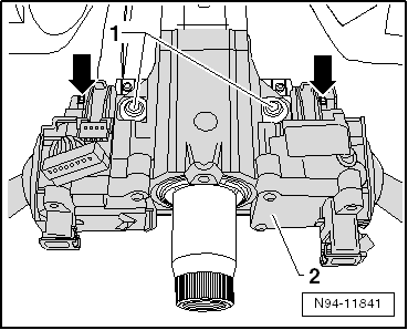
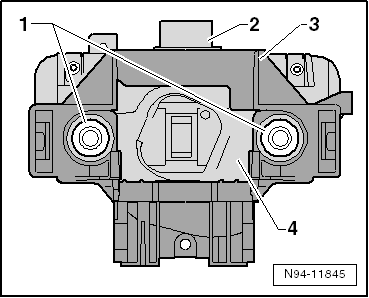
- Drill out the shear bolts -1- of the Electronic Steering Column Lock Control Module -J764--4-.

Note
M8 bolts -1-, hole diameter 6.8 mm.
- Disconnect the connector -2- on the back of the Electronic Steering Column Lock Control Module -J764--4- and then remove the Electronic Steering Column Lock Control Module -J764- and steering column switch mount -3- from the steering column.
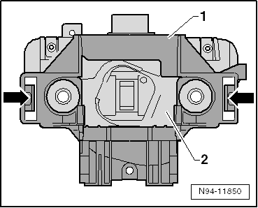
- Open both retainers -arrows- on the steering column switch mount and remove the mount -1- from the Electronic Steering Column Lock Control Module -J764--2-.
Installing
- Install the steering column switch mount -1- on the Electronic Steering Column Lock Control Module -J764--2- until it locks in place.
- Slide the Steering Column Combination Switch -E595- onto the steering column switch mount and install the lower mounting bolt.
- Slide the pre-assembled unit of the Electronic Steering Column Lock Control Module -J764-, the steering column switch mount and the Steering Column Combination Switch -E595- straight onto the steering column all the way and align it with respect to the threaded holes.

- Attach the Electronic Steering Column Lock Control Module -J764--4- to the steering column with new shear bolts -1-.
- Tighten the new shear bolts -1- until the bolt heads shear off.
- Install all components accordingly in the reverse order.
Note
Code the new Electronic Steering Column Lock Control Module -J764- after installing.
 Steering Column Combination Switch -E595-
General Information
Depending on vehicle equipment, the Steering Column Combination Switch -E595-
consists of the following components and cannot be disassembled:
Turn Signal Switch -E2-
Windshiel ...
 Electronic Steering Column Lock Control Module -J764-
General Information
If the vehicle has "Keyless Access" keyless locking and starting system, the
steering column does not lock mechanically via the lock cylinder, but rather it
locks electrically (E ...
See More:
Volkswagen Tiguan Owners Manual > Vehicle battery: Introduction to the subject
In this chapter you will find information on the following subjects:⇒ Warning
light
⇒ Checking the vehicle battery electrolyte level ⇒ Charging, replacing, disconnecting
and connecting the 12 Volt vehicle battery
The standard 12 Volt vehicle battery is part of the vehicle electri ...
Volkswagen Tiguan Owners Manual
Volkswagen Tiguan Service and Repair Manual
- Body exterior
- Body Interior
- General Paint Information
- Paint
- Brake System
- Suspension, Wheels, Steering
- Wheel and Tire Guide
- Towing Guide
- Wheel and Tire Guide General Information
- Communication
- Electrical Equipment General Information
- Electrical Equipment from 06/2011
- Heating, Ventilation and Air Conditioning
- Refrigerant R134a Servicing
- 6-Speed Manual Transmission 02Q, OBB, and OFB
