Volkswagen Tiguan Service and Repair Manual: Windshield Wiper System
General Information
Caution
Always follow the procedure as described in the Repair Manual when disconnecting and connecting the battery.
Note
Additional information:- Refer to the Owner's Manual.
- Refer to Self Study Program; No 404; The Tiguan.
The Wiper Motor Control Module -J400- is integrated with the Windshield Wiper Motor -V-. If the Wiper Motor Control Module -J400- is to be exchanged, read the coding beforehand and then code the new Wiper Motor Control Module -J400- with this value.
To remove wiper blades, wiper arms must be put into "service/winter position". The "service/winter position" is activated by pressing the windshield wiper lever in the "one-touch wiping" position within 10 seconds after switching the ignition off Owner's Manual.
Malfunction Recognition and Malfunction Indicator:
The Vehicle Electrical System Control Module -J519- is equipped with On Board Diagnostics (OBD) which assists troubleshooting.
Use the Vehicle Diagnostic Tester in "Guided Fault Finding".
Windshield Wiper Motor, Deactivating Alternating Park Position Function
Windshield wiper system is equipped with APP function (alternating park position).
The APP function causes the wiper, after every second time it is switched off, to move up one level after reaching the lowest position.
To install the wiper arm on the linkage, the motor must be switched off in the lower park position. This is attained by deactivating the APP function (code Wiper Motor Control Module -J400-) using the Vehicle Diagnostic Tester.
Note
- An activation of APP function is not possible.
- APP function is automatically activated after 100 wiping cycles. This applies to wiper motors in which the APP function was deactivated as well as for new wiper motors.
Overview - Windshield Wiper System
- Mounting Nuts, Wiper Arm to Linkage
- 20 Nm
- Joint-Free Windshield Wiper
- Removing and installing.
- Park position, adjusting.
- Wiper Arms
- Removing and installing.
- Bolts for Wiper Frame with Linkage To Body
- 8 Nm
- Wiper Frame with Linkage
- Removing and installing.
- Windshield Wiper Motor -V- with Wiper Motor Control Module -J400-
- Removing and installing.
- Wiper Motor Control Module, coding/APP function, deactivating.
- Bolts connecting the wiper motor to the wiper frame with linkage - 8 Nm
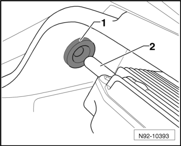
- Rubber Grommet in Bulkhead
- Note installation instructions.
Wiper Arms, Removing and Installing
Special tools and workshop equipment required
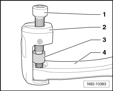
- Puller - Wiper Arm Kit - Puller 1 -T10369/1-
Removing
- Pry out the caps -arrows- using a screwdriver.

- Remove the nuts -arrows-.
- Slide the arms of the Puller - Wiper Arm Kit - Puller 1 -T10369/1--2- under the wiper arm -4- as shown in the illustration.
Caution
The windshield wiper shaft can be damaged.
Always use the thrust piece -3- to loosen the windshield wiper arm.
- Turn the pressure bolt -1- on the puller clockwise until the thrust piece -3- makes contact with the wiper shaft. Using a 6 mm socket head wrench, rotate the pressure bolt -1- on the puller clockwise until the wiper arm -4- is loosens from the shaft.
- Remove the puller and the wiper arm.
- Repeat this procedure on the second windshield wiper arm.
Installing
Install in reverse order of removal. Note the following:
- Deactivate the APP function.
Note
The wipers cannot be activated when the hood is open and the vehicle is at standstill.
- Close the hood.
Note
Move the wiper motor to the end position, switch on the ignition, and briefly press the steering column lever down 1x (single-wipe mode).
- Move the wiper motor to the end position.
- Switch the ignition off again once the wiper motor shuts off.
- Open the hood.
Note
Tighten the wiper arm nuts to the tightening specification only after setting the wiper blade park position.
- Mount the wiper arms on the wiper arm shafts in the end position and tighten the mounting nuts -arrows- hand-tight.
- Adjust windshield wiper blade park position.

Windshield Wiper System, Removing and Installing
Special tools and workshop equipment required
- Torque Wrench 1331 5-50Nm -VAG1331-
Caution
Always follow the procedure as described in the Repair Manual when disconnecting and connecting the battery.
Note
The Wiper Motor Control Module -J400- is integrated with the Windshield Wiper Motor -V-. If the Wiper Motor Control Module -J400- is to be exchanged, read the coding beforehand and then code the new Wiper Motor Control Module -J400- with this value.
Removing
- Deactivate the APP function.
- Let the wiper arms return to their park position and then turn off the ignition.
- Disconnect the battery.
- Remove the wiper arms.
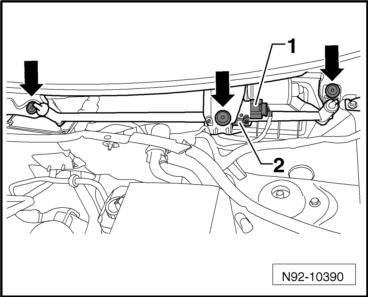
- Remove the plenum chamber cover.
- Disconnect the connector -1-.
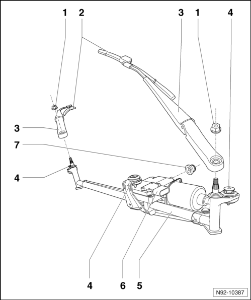
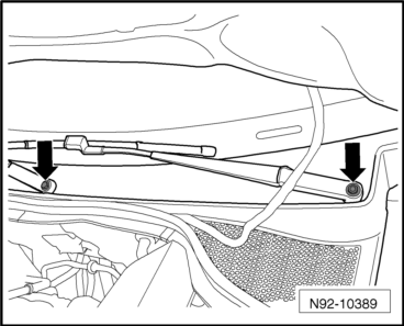
- Remove the bolts -arrows- and remove the wiper frame with the motor -2- from the vehicle.

Installing
Install in reverse order of removal. Note the following:
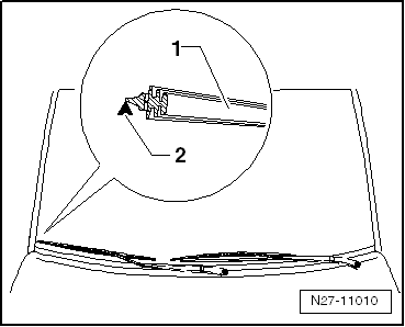
- Insert the wiper frame with linkage and wiper motor into the plenum chamber.
- Insert the guide pin -2- of the wiper frame during installation into the rubber grommet -1- in the bulkhead.
- Screw in the mounting bolts -arrows- and tighten to the tightening specification given in the assembly overview.
- Connect the connector -1- to the wiper motor and lock it.
- Install the plenum chamber cover.
- Connect the battery.
- Install the windshield wiper arms.
Wiper Motor from Wiper Frame, Removing and Installing
Special tools and workshop equipment required
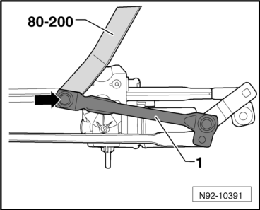
- Pry Lever -80-200-
- Torque Wrench 1331 5-50Nm -VAG1331-
Removing
- Remove the windshield wiper system.
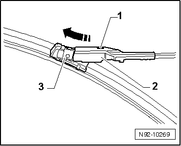
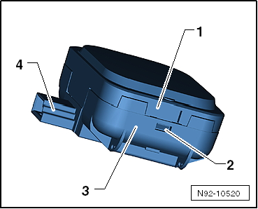
- Pry the linkage -1- off the motor crank ball head -arrow- using Pry Lever -80-200-.

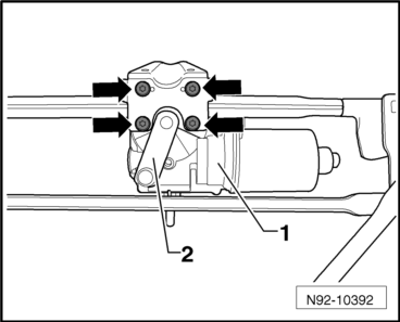
- Turn the motor crank -2- and remove the 4 bolts -arrows-.
- Remove the windshield wiper motor and control module -1- from the wiper frame.
Installing
- Install the windshield wiper motor and control module -1- in the wiper frame and secure it with the 4 bolts -arrows-.
- Tighten the threaded connections to the tightening specifications given in the assembly overview.

- Turn the motor crank back to its original position until the crank and the linkage -1- are over each other in the same angle.
- Push the linkage -1- onto the motor crank ball head -arrow-.
Windshield Wiper Blades, Adjusting Park Position
Special tools and workshop equipment required
- Torque Wrench 1331 5-50Nm -VAG1331-
- Deactivate the APP function.
- Let the wiper return to its park position and then turn off the ignition.
- Adjust the wiper blade park position.
Driver Side
Note
The adjustment dimension for the wiper blade park position -a- is measured and adjusted on the driver side between the center of the wiper blade -1- and the upper edge of the plenum chamber cover -2-.
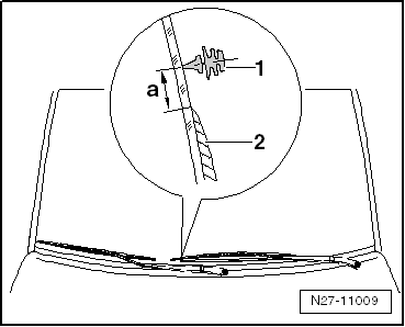
Distance -A- between tips of wiper lips and upper edge of plenum chamber cover must be 10 mm.
- If necessary, adjust the wiper blade park position by repositioning the wiper arm.
- Tighten the threaded connections to the tightening specifications given in the assembly overview.
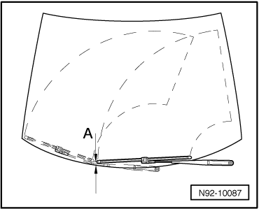
Passenger Side
Note
Due to the contour of the windshield in the adjustment range, the center of the wiper blade must be aligned with an arrow on the windshield on the front passenger side.
- Align the center of the wiper blade -1- with the arrow on the windshield -2-.
- If necessary, adjust the wiper blade park position by repositioning the wiper arm.
- Tighten the threaded connections to the tightening specifications given in the assembly overview.
Joint-Free Windshield Wiper
Joint-Free Windshield Wiper, Removing and Installing
Removing
Note
- Be careful not to confuse the driver side and front passenger side wiper blades when installing them.
- Joint-free wiper blades are very flexible. When lifting the wiper blades away from the windshield, only grasp them in the area of the wiper blade mount.
- To remove wiper blades, wiper arms must be put into "service/winter position". The "service/winter position" is activated by operating windshield wiper lever in "one-touch wiping" setting within 10 seconds after switching off the ignition.
- Move the wiper arms to the "service/winter position".
- Fold up the wiper arm.
- Press the button -1- and remove the wiper blade mount -3- from the wiper arm -2- in the direction of -arrow-.
Installing
Install in reverse order of removal. Note the following:
- Slide the wiper blade mount -3- all the way into the wiper arm -2-.
- Make sure that the button -1- in the wiper arm -2- is securely engaged.
- Carefully fold the wiper arm back onto the windshield.

Wiper Blades, Removing and Installing, Joint-Free Blades
Note
See the "Joint-free wiper blade characteristics" chapter in the "Electrical equipment general information" repair manual in ELSA.
- Remove the joint-free windshield wiper.
- Check on which side the wiper blade insert cannot slide into guide.
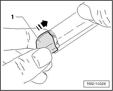
- Carefully pry out the cap -1- on the side on which the wiper blade cannot slide into the guide.
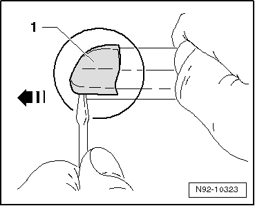
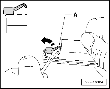
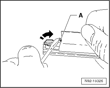
- Using a suitable screwdriver, open the wiper blade retainer -A- by bending it up.
- Replace the wiper blade.
Note
Make sure that the wiper blade is seated correctly in the wiper blade guides.
- Press the wiper blade retainer -A- back down with a suitable screwdriver until the wiper blade can no longer slide into the guide.
- Install the new cap -1- and check for secure seating.
- Install the joint-free windshield wiper.
- Check the wiper blade for proper functioning.
Rain/Light Recognition Sensor -G397-
Rain/Light Recognition Sensor -G397-, Removing and Installing
The rain/light recognition sensor is designed so that it can be used again. The only requirement to use it again is that the connecting pad must not be damaged.
Caution
Store the removed Rain/Light Recognition Sensor -G397- is in a dust-free area and keep the silicone connecting pads from getting dirty.
Note
- If the rain sensor was replaced by another rain sensor having a different part number, it is necessary to code the new rain sensor.
- Rain sensors cannot be interchanged. Refer to the Parts Catalog for the correct rain sensor.
Removing
- Switch off the ignition and all electrical consumers and remove the ignition key.
- Remove the interior rearview mirror.
- Disconnect the connector -A- from the Rain/Light Recognition Sensor -G397--1-.
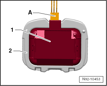
- Pry the Rain/Light Recognition Sensor -G397--1- by the opening -3- out of the retaining plate -2- carefully using a screwdriver.

Note
During removal, pry off the complete Rain/Light Recognition Sensor -G397- and not just the upper shell of the sensor.
Installing
Install in reverse order of removal. Note the following:
Caution
- Always clean the windshield surface inside the Rain/Light Recognition Sensor -G397- bracket before installing. Remove any traces of the connecting pad still remaining on the windshield.
- Surface (connecting pads) of Rain/Light Recognition Sensor -G397- must not be contaminated or damaged when installing. Always replace a sensor that has a damaged connecting pad.
Note
If the surface (connecting pads) of Rain/Light Recognition Sensor -G397- is soiled, it can be potentially cleaned by "applying" and then "pulling off" one or more adhesive strips.
- Clean the windshield thoroughly around the retaining plate, cleaning solution.
- Remove the cap from the new Rain/Light Recognition Sensor -G397-, if necessary.
- Insert the Rain/Light Recognition Sensor -G397--1- into the retaining plate on the windshield -2- and then press it in securely.
Note
Even if the sensor is installed correctly, small air bubbles can form between the windshield and the connecting pad. The contact surface must be free-of-bubbles after approximately 10 minutes.
- Connect the connector -A- and then install a wire cover to secure the rain sensor.
- Install the interior rearview mirror.
- Code the Rain/Light Recognition Sensor -G397-, if necessary.

Rain/Light Recognition Sensor -G397-, Servicing, Manufacturer TRW
Only TRW can replace the housing and optical unit if the optical unit (coupling cushion) is damaged.
There are different housings for the rain sensors because there are multiple manufacturers.
A replacement rain sensor housing and optical unit are always delivered with mounting clips. Remove these clips if they are not needed.
Perform the Following
- Remove the rain sensor.
Caution
The rain sensor electronics may be damaged.Be careful not to insert the screwdriver all the way through the housing up to the rain sensor electronics.
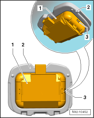
Do not touch the rain sensor electronics.- Press the tab -2- on both sides and separate the upper section -1- with optical unit from the lower section -3-.
- Remove the rain sensor electronics at the connector -4- from the old lower section and install the new electronics the exact same way.
Caution
Do not touch the optical unit.
Remove the protective cover from the rain sensor just before installing it.
- Assemble the new housing upper section with optical unit and protective cover with the housing lower section.
- Install the rain sensor.
Rain/Light Recognition Sensor -G397-, Coding
- Code the Rain/Light Recognition Sensor -G397- using the Vehicle Diagnostic Tester.

 Windshield Washer System
General Information
NoteAdditional information:
Refer to the Owner's Manual.
Refer to Self Study Program; No 404; The Tiguan.
Refer to
→ Wiring diagrams, Troubleshooting & Component loc ...
See More:
Volkswagen Tiguan Service and Repair Manual > Communication: Sound System Amplifier
General Information
Note
Before troubleshooting or servicing, the technicians must be familiar
with the function and operation of the radio and radio navigation system.
Refer to the Owner's Manual.
Use the Vehicle Diagnostic Tester"Guided Fault Finding" function and
→ Wiring diagrams, ...
Volkswagen Tiguan Owners Manual
Volkswagen Tiguan Service and Repair Manual
- Body exterior
- Body Interior
- General Paint Information
- Paint
- Brake System
- Suspension, Wheels, Steering
- Wheel and Tire Guide
- Towing Guide
- Wheel and Tire Guide General Information
- Communication
- Electrical Equipment General Information
- Electrical Equipment from 06/2011
- Heating, Ventilation and Air Conditioning
- Refrigerant R134a Servicing
- 6-Speed Manual Transmission 02Q, OBB, and OFB
