Volkswagen Tiguan Service and Repair Manual: Electro-Mechanical Steering Gear
Overview - Electro-Mechanical Steering Gear
Caution
If the universal joint is separated from the steering gear, the following work cannot be performed:
- Connect the battery.
- Switching on the ignition
- Turning the steering gear
- Turning the steering column.
These points must be observed since performing these actions could cause irreparable damage.
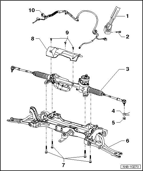
- Universal Joint
- Bolt
- 30 Nm
- Always replace if removed
- M8 x 35
- Power Steering Gear
- With Power Steering Control Module -J500-
- With Electromechanical Power Steering Motor -V187-
- With Engine Speed Sensor -G28-
- With Steering Torque Sensor -G269-
- Can be checked in Guided Fault Finding using the Vehicle Diagnostic Tester.
- Removing and installing.
Note
Correct any faults stored in the DTC memory before replacing the steering gear using the Vehicle Diagnostic Tester.
- Wheel Bearing Housing
- Nut
- 50 Nm
- Always replace if removed
- M12 x 1.5
- Self-locking
- Subframe
- Bolt
- 50 Nm + 90º
- Always replace if removed
- M10 x 70
- Heat Shield
- TORX Bolt
- 6 Nm
- Self-tapping
- Wire
Steering Gear, Removing and Installing
Special tools and workshop equipment required
- Torque Wrench 1331 5-50Nm -VAG1331-
- Torque Wrench 1332 40-200Nm -VAG1332-
- Engine and Gearbox Jack -VAS6931-
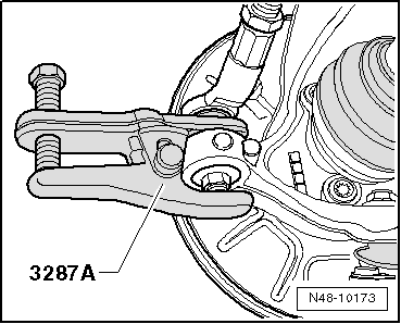
- Puller - Ball Joint -3287A-
Removing
Note
Correct any faults stored in the DTC memory before replacing the steering gear using the Vehicle Diagnostic Tester.
- Connect the Vehicle Diagnostic Tester and start "Guided Fault Finding".
Follow the instructions on the screen.
- Turn the steering wheel in the straight position and remove the ignition key so that the steering wheel lock engages.
Vehicles with "Keyless Access" Keyless Locking and Starting System
Switch the ignition off and open the driver door so the steering wheel lock engages.
Continuation for All Vehicles
- Disconnect the battery.
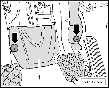
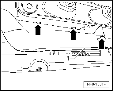
- Remove foot well trim -1-, unscrew nuts -arrows- to do so.
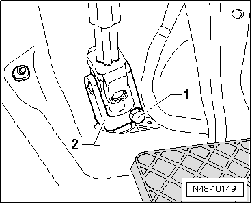
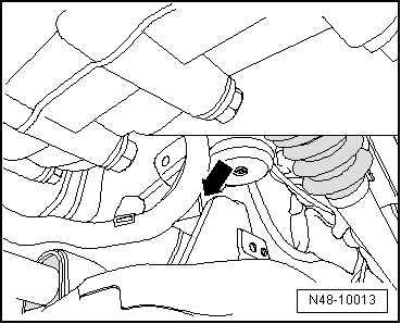
- Remove the bolt -1- and remove the universal joint -2- from the steering gear.
Caution
If the universal joint is separated from the steering gear, the following work cannot be performed:
- Connect the battery.
- Switching on the ignition
- Turning the steering gear
- Turning the steering column.
These points must be observed since performing these actions could cause irreparable damage.
- Remove the front wheels.
- Loosen the nut of the tie rod end, but do not remove yet.
Caution
To protect the thread, screw the nut on the pin a few turns.
- Press off tie rod end from wheel bearing housing with Puller - Ball Joint -3287A- and then remove nut.
- Remove the lower noise insulation.
- Remove coupling rods from stabilizer.
- Remove the nuts -arrows-.
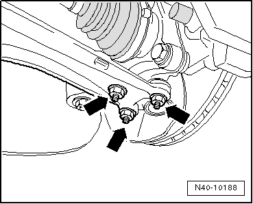
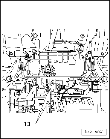
- Remove the bolts -13- and then remove the pendulum support from the transmission.
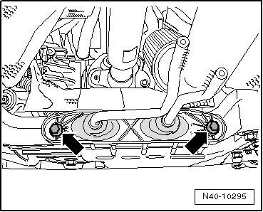
- Remove exhaust system bracket from the subframe-arrows-.
FWD vehicles
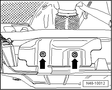
- Remove bolts -arrows- from heat shield.
- Remove heat shield from subframe.
Continuation for All Vehicles
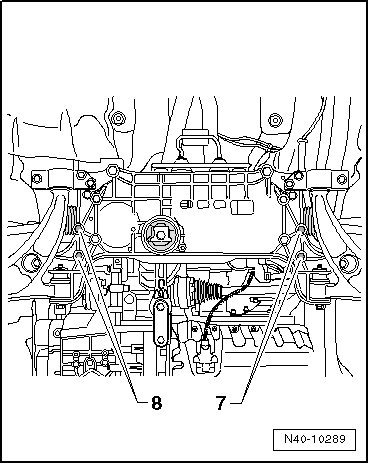
- Remove the bolts -5 and 6- on the steering gear.

- Remove the stabilizer bar bolts -7 and 8-.
- Secure the subframe.
- Disconnect the connector for the service interval extension to the oil pan.
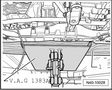
- Place the Engine/Gearbox Jack -VAG1383A- under the subframe.
- Place for example a block of wood -1- between Engine/Gearbox Jack -VAG1383A- and the subframe.
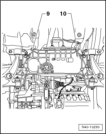
- Remove the bolts -9 and 10- and slightly lower the subframe. Pay attention the electrical wiring while doing this.
- Remove heat shield -1- above exhaust system.
- Remove bolts -arrows-.
- Remove cable guide from subframe -arrow-.
- Unclip all other cable mounting points on steering gear.
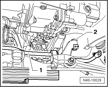
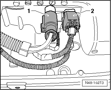
- Disconnect the connectors -1 and 2- from the steering gear.
- Carefully lower the subframe using Engine and Gearbox Jack -VAS6931-.

- Now, lift the stabilizer bar -1- toward the front, over the subframe -2- and down, while turning the stabilizer bar slightly.
- Lift down steering gear from subframe.
- Set down steering gear as depicted in the illustration.
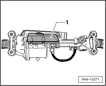
This prevents damage to the control module -1-.
Installing
Install in reverse order of removal.
- Make sure the white pressure membrane -arrow- is clean and not damaged.
- If necessary, carefully clean the pressure membrane.
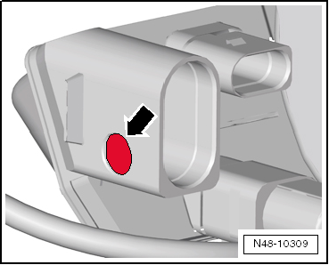
Note
If the pressure membrane is damaged, then the steering gear must be replaced.
- Connect the connectors -1 and 2- so that they audibly click into place.
The threaded sleeve must seat in subframe hole.
Note
- Coat the seal on the steering gear with lubricant such as soft soap before installing the steering gear.
- After placing steering gear onto universal joint, make sure that seal on steering gear makes contact on assembly plate without kinks and opening to footwell is correctly sealed. Ingress of water and/or noises may be the result.
- Make sure sealing surfaces are clean.
Before fastening the bolts for subframe, position steering gear on subframe and fasten bolts for steering gear and stabilizer.
- Install the lower noise insulation.
- Bolt the universal joint to the steering gear.
- Connect the battery.
- Perform the Steering Angle Sensor -G85- basic setting using the Vehicle Diagnostic Tester.
It is necessary to adapt the electro-mechanical power steering using the Vehicle Diagnostic Tester if new steering gear was installed.
- Adapt the electro-mechanical power steering with the Vehicle Diagnostic Tester.
Chassis
Electromechanical power steering
01 - OBD-capable system
Electro-mechanical power steering
Functions
Adapting electro-mechanical steering
Follow the instructions on the screen.
Note
If the vehicle is equipped with park assist 2, then the Power Steering Control Module -J500- must be coded again. Refer to Vehicle Diagnostic Tester.
After installation, position of steering wheel must be checked with a road test.
If steering wheel is at an angle or a new steering gear was installed, vehicle must be aligned.
- Perform a vehicle alignment.
Tightening Specifications
| Component | Tightening Specification |
Mounting bracket to body
|
70 Nm + 180º |
Stabilizer bar to
subframe
|
20 Nm + 90º |
Stabilizer bar to
coupling rod
|
65 Nm |
Ball joint to aluminum
control arm:
|
60 Nm |
Ball joint to sheet steel
control arm
|
100 Nm |
Shield to subframe
|
6 Nm |
Steering gear to subframe
|
50 Nm + 90º |
Universal joint to
steering gear
|
30 Nm |
Shield to steering gear
|
6 Nm |
Tie rod end to wheel
bearing housing
|
50 Nm |
| Exhaust system bracket to subframe | |
Tightening Specifications, Subframe to Body
| Bolt | Tightening Specification |
M12 x 1.5 x 90
|
70 Nm + 180º |
M12 x 1.5 x 100
|
70 Nm + 180º |
M12 x 1.5 x 110
|
70 Nm + 90º |
Tightening Specifications, Pendulum Support to the Transmission
| Bolt | Tightening Specification |
M10 x 35
|
50 Nm + 90º |
M10 x 75
|
50 Nm + 90º |
M12 x 1.5 x 85
|
60 Nm + 90º |
 Steering Column and Steering Wheel
Overview - Steering Column
Note
Welding and straightening work on supporting or wheel carrying
components of suspension is not permitted.
Always replace self-locking nuts.
Always replace corrode ...
 Electro-Mechanical Steering Gear, Servicing
Overview - Electro-Mechanical Steering Gear
Currently, there is no service work to be performed on steering gear.
Right Tie Rod End
Checking.
Allocation. Refer to the Parts Catalog.
Nut
...
See More:
Volkswagen Tiguan Owners Manual > Wheel covers: Wheel bolt caps
Fig. 191 Pulling cover caps off wheel
bolts.
Read and follow the introductory information and
safety information first⇒Introduction
to the subject
Take the wire clip out of the vehicle tool kit ⇒ Vehicle tool kit .
Insert the wire clip through the opening of the cover cap ⇒ ...
Volkswagen Tiguan Owners Manual
Volkswagen Tiguan Service and Repair Manual
- Body exterior
- Body Interior
- General Paint Information
- Paint
- Brake System
- Suspension, Wheels, Steering
- Wheel and Tire Guide
- Towing Guide
- Wheel and Tire Guide General Information
- Communication
- Electrical Equipment General Information
- Electrical Equipment from 06/2011
- Heating, Ventilation and Air Conditioning
- Refrigerant R134a Servicing
- 6-Speed Manual Transmission 02Q, OBB, and OFB
