Volkswagen Tiguan Service and Repair Manual: Adaptive Chassis DCC Suspension Strut
Overview - Adaptive Chassis DCC Suspension Strut
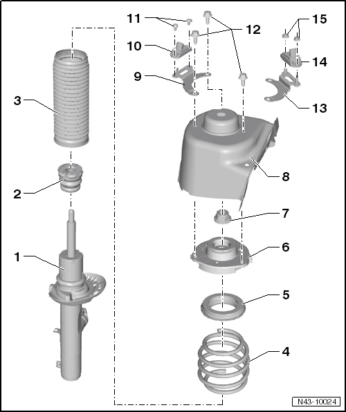
- Shock Absorber with Left Front Damping Adjustment Valve -N336-
- Can be replaced individually
- Allocation. Refer to the Parts Catalog.
- Stop Buffer
- Allocation. Refer to the Parts Catalog.
- Protective Cover
- Coil Spring
- Removing and installing.
- Note the color code
- Allocation. Refer to the Parts Catalog.
Spring allocation via PR No.
These numbers can be found on vehicle data plate.
- Surface of spring coil may not be damaged
- Deep-Groove Ball Bearing
- Strut Mount
- Note the installation position.
- Hex Nut
- 60 Nm
- Always replace if removed
- M14 x 1.5
- Self-locking
- Suspension Strut Tower
- Bracket
- For the Left Front Body Acceleration Sensor -G341-
- Removing and installing.
- An "L" is stamped on the retainer
Note
Be sure to use the correct retainer.
- Left Front Body Acceleration Sensor -G341-
- Removing and installing.
- Note the installation position of the retainer
- Bolt
- 5 Nm
- Always replace if removed
- Bolt
- 15 Nm + 90º additional turn
- Always replace if removed
- M8 x 26
- Bracket
- For the Right Front Body Acceleration Sensor -G342-
- Removing and installing.
- An "R" is stamped on the retainer
- Right Front Body Acceleration Sensor -G342-
- Removing and installing.
- Note the installation position of the retainer -item 13-
- Nut
- 5 Nm
- Always replace if removed
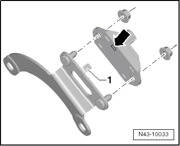
Installation Position Left Front Body Acceleration Sensor -G341- on the Retainer
The tab on the retainer -1- must fit into the recess in the Left Front Body Acceleration Sensor -G341--arrow-.
Note
Be sure to use the correct retainer. An "LA" is stamped on the retainer
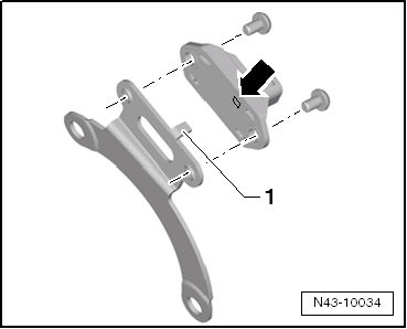
Installation Position Right Front Body Acceleration Sensor -G342- on the Retainer
The tab on the retainer -1- must fit into the recess in the Right Front Body Acceleration Sensor -G342--arrow-.
Note
Be sure to use the correct retainer. An "R" is stamped on the retainer.
Adaptive Chassis DCC Suspension Strut, Removing and Installing
Special tools and workshop equipment required
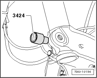
- Spreader Tool -3424-
- Torque Wrench 1332 40-200Nm -VAG1332-
- Engine and Gearbox Jack -VAS6931-
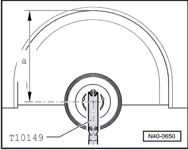
- Engine/Gearbox Jack Adapter - Wheel Hub Support -T10149-
- Torque Wrench 1331 5-50Nm -VAG1331-
- Drive Shaft Remover -T10520-
Removing
- Loosen drive axle bolt on the wheel hub.
- Remove the wheel.
- Remove the level control system sensor from the control arm.
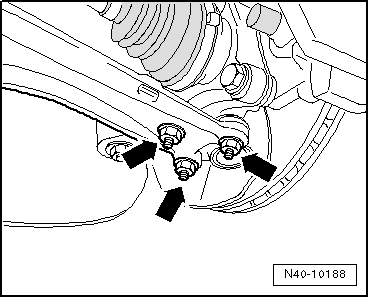
- Remove the nut -arrow- of the connecting link from suspension strut.
- Remove the nuts -arrows-.
- Remove the wheel bearing housing with the ball joint from the control arm.
- Remove the drive axle outer joint from the wheel hub.
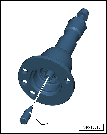
If the drive axle cannot be pulled out of the wheel bearing, then the drive axle can be pushed out of the wheel bearing using the Drive Shaft Remover -T10520-.
Before using the Drive Shaft Remover -T10520-, make sure that the thrust piece -1- is installed.
Using the Drive Shaft Remover -T10520-:
- Secure the Drive Shaft Remover -T10520--1- with three wheel bolts -2- on the wheel hub, so that the drive axle -3- can be pressed out.
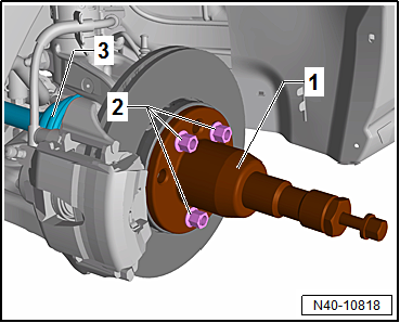
- Follow the specified sequence exactly.
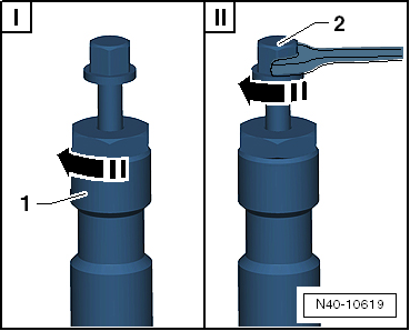
- Tighten the knurled nut -1- hand-tight.
- Only turn the bolt -2- using a wrench and press out the drive axle using the Drive Shaft Remover -T10520-.
Note
At the end of the tasks or to set back, the spindles must be brought back into the original position so that the hydraulic operation can be used.
- Secure the drive axle to the body using wire.
Note
The drive axle must not hang down, otherwise the inner joint will be damaged by over bending.
- Bolt the ball joint to the control arm again.
- Secure the Engine and Gearbox Jack -VAS6931- using the Engine/Gearbox Jack Adapter - Wheel Hub Support -T10149- to the wheel hub with a wheel bolt.
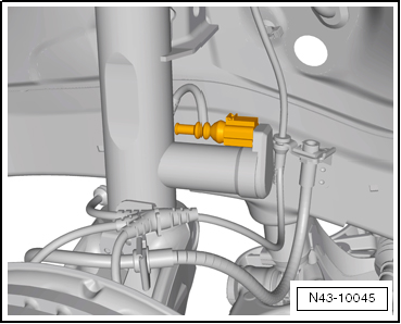
- Disconnect the connector and remove the wire from the suspension strut
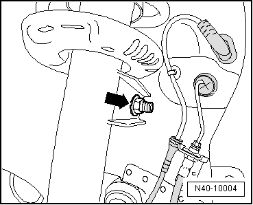
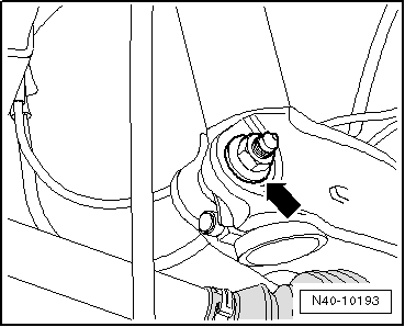
- Disconnect the threaded connection for the wheel bearing housing/suspension strut nut -arrow-.

- Insert Spreader Tool -3424- into wheel bearing housing slot.
- Turn the ratchet 90º and remove it from the Spreader Tool -3424-.
- Press the brake rotor toward the suspension strut by hand.
Otherwise strut tube may be canted in hole of wheel bearing housing.
- Pull off wheel bearing housing downward from strut tube and lower using Engine/Gearbox Jack -VAG1383A- as far until strut tube hangs freely.
- Tightly tie wheel bearing housing to console/subframe using binding wire.
- Remove the Engine and Gearbox Jack -VAS6931- from under the wheel bearing housing.
- Remove the wiper arms.
- Remove the plenum chamber cover.
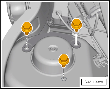
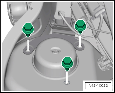
- Remove the hex bolts for the upper strut mount and remove suspension strut.
Installing
- Secure the Engine and Gearbox Jack -VAS6931- using the Engine/Gearbox Jack Adapter - Wheel Hub Support -T10149- to the wheel hub with a wheel bolt.
- Attach suspension strut to wheel bearing housing and secure suspension strut using socket head bolt and new nut.

The point of the internal multi-point bolt must face the direction of travel
- Remove the Spreader Tool -3424-.
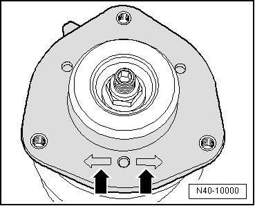
One of two markings -arrows- on the spring plate must point in the direction of travel.
Left Suspension Strut
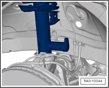
The suspension strut must be installed so that the Left Front Damping Adjustment Valve -N336- faces opposite the drive direction.
Right Suspension Strut
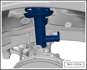
The suspension strut must be installed so that the Right Front Dampening Adjustment Valve -N337- faces opposite the drive direction.
Continuation for Both Sides
- Check the installation position of the Left and Right Front Body Acceleration Sensor -G341/G342- retainer.
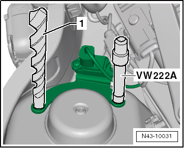
Note
- Use an 11 mm drill -1- and the Pilot Drift -VW222A- to check the installation position.
- The holes in the retainer must align with the holes in the shock absorber dome.
- Remove wire on wheel bearing housing.
- Carefully lift the wheel bearing housing with the transmission jack enough so that the suspension strut/strut tower bolts can be installed.
If necessary, use ladder, for example the Step Ladder -VAS5085- to install bolts.
- Tighten the hex bolts for the upper strut mount.
- Remove the Engine/Gearbox Jack Adapter - Wheel Hub Support -T10149-.
- Tighten the threaded connection on the wheel bearing housing/suspension strut -arrow-.
- Remove the nuts -arrows-.
- Insert the drive axle into the wheel hub.
- Insert the wheel bearing housing with the ball joint into the control arm.
- Attach the ball joint to the control arm -arrows-.
Note
Make sure the ball joint boot is not damaged or twisted.
- Connect the level control system sensor to the control arm.
Note
- The level control system sensor lever must point toward vehicle exterior.
- The thread on the vehicle level sensor must be installed into the front hole in the control arm. The tab on the vehicle level sensor retainer must lock into the rear hole in order to assure a correct installation position.

- Connect the connector to the Left and Right Front Dampening Adjustment Valve -N336/N337-.
- Tighten drive axle bolt onto the wheel hub.
Note
Vehicle must not be standing on its wheels when doing this, otherwise wheel bearing will be damaged.
- Install the plenum chamber cover.
- Install the wiper arms.
Install in reverse order of removal.
- Install the wheel and tighten.
Tightening Specifications
| Component | Tightening Specification |
Suspension strut to wheel
bearing housing
|
70 Nm + 90º |
Suspension strut to body
(suspension strut tower)
|
15 Nm + 90º |
Ball joint to aluminum
control arm:
|
60 Nm |
Ball joint to sheet steel
control arm
|
100 Nm |
Connecting link to
suspension strut
|
65 Nm |
Drive axle to wheel hub
|
70 Nm + 90º |
| Level control system sensor to the control arm | 9 Nm |
 Adaptive Chassis DCC, Components
Overview - Adaptive Chassis DCC, Components
Caution
The body acceleration sensors may not be interchanged with each other.
Damping Adjustment Button -E387-
Component location: in front of the ge ...
 Adaptive Chassis DCC Shock Absorber, FWD
Overview - Adaptive Chassis DCC Shock Absorber, FWD
Lower Spring Support
Spring end rotated up to stop
Coil Spring
There are different suspension versions.
Removing and installing.
...
See More:
Volkswagen Tiguan Service and Repair Manual > Heating, Ventilation: Display Control Head
Display Control Head, Removing and Installing
Removing
Note
The controls consist of two separable housings. Before removing
controls, bring rotary buttons into the following positions:
Heater control to "cold"
Blower to "0"
Air flow direction to "footwell"
Remove the trim from the heater ...
Volkswagen Tiguan Owners Manual
Volkswagen Tiguan Service and Repair Manual
- Body exterior
- Body Interior
- General Paint Information
- Paint
- Brake System
- Suspension, Wheels, Steering
- Wheel and Tire Guide
- Towing Guide
- Wheel and Tire Guide General Information
- Communication
- Electrical Equipment General Information
- Electrical Equipment from 06/2011
- Heating, Ventilation and Air Conditioning
- Refrigerant R134a Servicing
- 6-Speed Manual Transmission 02Q, OBB, and OFB
