Volkswagen Tiguan Service and Repair Manual: Subframe, Servicing, from 05/28/2012
Front Bonded Rubber Bushing, Replacing
Special tools and workshop equipment required
- Tensioning Strap -T10038-
- Hydraulic Press - Rear Subframe Bushing Tool Kit -T10263-
- Subframe Bushing Assembly Tool Kit -T10356-
- Engine and Gearbox Jack -VAS6931-
- Hydraulic Press -VAS6178- with Bearing Installer - Wheel Hub/Bearing Kit- Pressure Head -T10205/13-
- Pneumatic/Hydraulic Foot Pump -VAS6179-
- Bearing Installer - Wheel Hub/Bearing Kit -T10205-
Note
- If a bonded rubber bushing is faulty, then the bonded rubber bushing on the opposite side must also be replaced. Refer to the Parts Catalog for the allocation.
- Check the other bearing before switching out a defected bonded rubber bushing.
- If there are any tears or other visible damages, replace the bonded rubber bushing.
- In order to replace the rubber bonded bushing, the subframe must be lowered either at the front or at the rear. It is not necessary to remove the subframe.
- Identify mounting location to subframe before removing the bonded rubber bushing.
Pressing Out Bonded Rubber Bushing, Front
- Loosen the wheel bolts.
- Raise the vehicle.
- Remove the wheels.
- Remove the spring.
- Remove the rear muffler.
- Disconnect the electric connections between the rear axle and the body.
- Remove the stabilizer bar.
- Remove the tie rods.
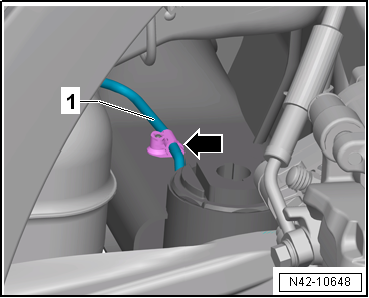
- Remove the clamps -1- on both sides of the vehicle.

Note
Do not disconnect the brake line.
- Secure both sides of the vehicle on the hoist arms using Tensioning Straps -T10038-.
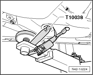
WARNING
The vehicle could slide off the hoist if it is not secured.
- Place the Engine and Gearbox Jack -VAS6931- with Universal Support Plate -VAG1359/2- below subframe and secure with strap.

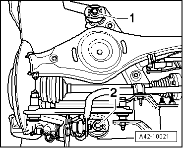
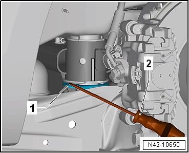
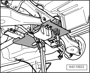
- Remove hex head bolt -1 or 2- on both sides.
Note
Only the left side of the vehicle is shown in the illustration.
To secure the subframe, Locating Pins -T10096- must be screwed in one after the other on both sides of the vehicle at positions -1 and 2-.
- Secure the position of the subframes using two Locating Pins -T10096- to 20 Nm.
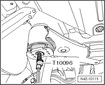
Note
Locating Pins -T10096- may only be tightened to a maximum of 20 Nm, since otherwise the threads of the locating bolts will be damaged.
- Replace the bolts of the subframe one after the other on both sides using Locating Pins -T10096- and tighten them to 20 Nm.
The subframe position is now secured.
- Mark the installation location of the bonded rubber bushing on the subframe with a felt-tip pen -1-.
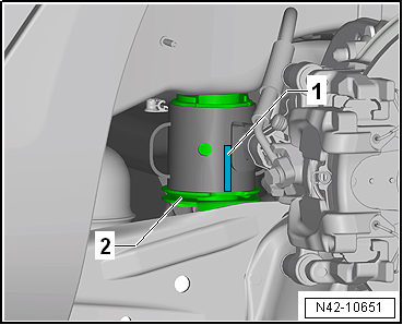
Note
Apply the mark -1- on the subframe in the middle of the recess on the bonded rubber mounting -2-.
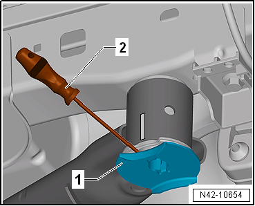
- Use a screwdriver -2- to pry off the anti-twist mechanism -1- near the bonded rubber bushing mounting retaining lugs.
- Lower the subframe approximately 100 mm using the Engine and Gearbox Jack -VAS6931-.
- Unclip the brake line -1- from the clip -arrow- on the left side.

Note
This will destroy the clip, so it will have to be replaced.
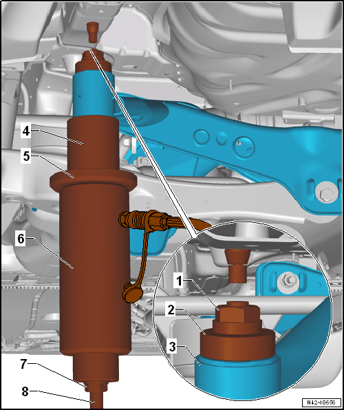
- Use the special tools as shown.
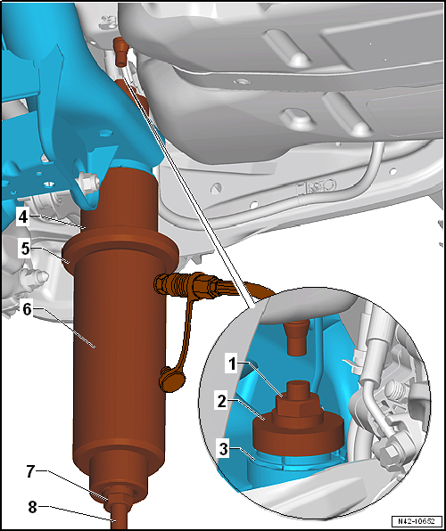
- Hydraulic Press - Rear Subframe Bushing Tool Kit - Nut -T10263/5-
- Subframe Bushing Assembly Tool Kit-Press Piece -T10356/1-
- Subframe
- Subframe Bushing Assembly Tool Kit-Pipe -T10356/2-, side with shoulder points to subframe
- Bearing Installer - Wheel Hub/Bearing Kit - Gripping Device -T10205/1-
- Hydraulic Press -VAS6178- with Bearing Installer - Wheel Hub/Bearing Kit- Pressure Head -T10205/13-
- Hydraulic Press - Rear Subframe Bushing Tool Kit - Nut -T10263/5-
- Hydraulic Press - Rear Subframe Bushing Tool Kit-Threaded Rod -T10263/4-
- Pretension special tools.
- Press out the bonded rubber bushing.
Note
- When removing the bonded rubber mounting, the bearing outer race is sheared off. There is a loud crack when this happens.
- After removing the bonded rubber bushing, it must be removed from the Tube -T10356/2- by tapping lightly with a hammer.
Press In on the Front Bonded Rubber Bushing
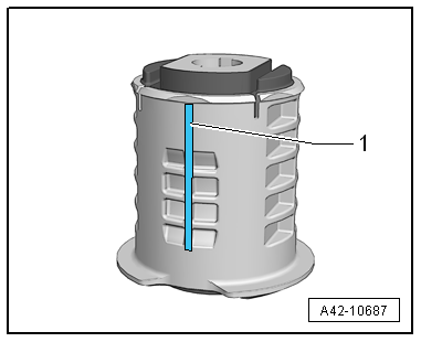
- Apply a line -1- on the vertical rib of the bonded rubber bushing to help mount.
- Apply mounting paste to the outer edge of the bonded rubber bushing.
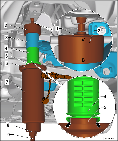
- Insert special tools with bonded rubber bushing into subframe as illustrated.
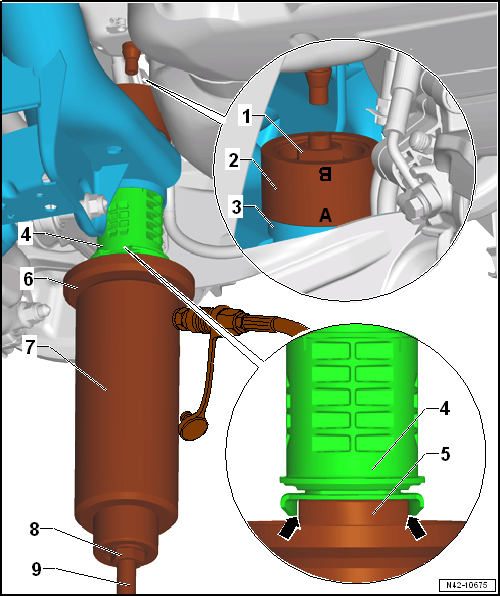
- Hydraulic Press - Rear Subframe Bushing Tool Kit - Nut -T10263/5-
- Subframe Bushing Assembly Tool Kit-Thrust piece -T10356/7- - the mark -A- points to the subframe
- Subframe
- Adjust the bonded rubber bushing to the marks (the marks need to align)
- Assembly Tool - Bushing -T10356/8- - the flattened sides need to fit into the cover of the bonded rubber bushing -arrows-.
- Bearing Installer - Wheel Hub/Bearing Kit - Gripping Device -T10205/1-
- Hydraulic Press -VAS6178- with Bearing Installer - Wheel Hub/Bearing Kit Pressure Head -T10205/13-
- Hydraulic Press - Rear Subframe Bushing Tool Kit - Nut -T10263/5-
- Hydraulic Press - Rear Subframe Bushing Tool Kit - Threaded Rod -T10263/4-
- Check the position of the bonded rubber bushing and, if necessary, align and pre-tighten special tools with bonded rubber bushing.
Note
- Make sure that the hose from the Hydraulic Press -VAS6178- to the Pneumatic/Hydraulic Foot Pump -VAS6179- runs between the trailing arm and the fuel tank when installed.
- Make sure that the bonded rubber bushing is not bent when installing. Otherwise the outer ring could become damaged.
- Operate the pump to press in the bonded rubber bushing until the shoulder is positioned on the subframe "without gap".
Install in reverse order of removal. Note the following:
Tightening Specifications
| Component | Tightening Specification |
Subframe to body
|
90 Nm +90º |
Rear Bonded Rubber Bushing, Replacing
Special tools and workshop equipment required
- Tensioning Strap -T10038-
- Hydraulic Press - Rear Subframe Bushing Tool Kit -T10263-
- Subframe Bushing Assembly Tool Kit -T10356-
- Engine and Gearbox Jack -VAS6931-
- Hydraulic Press -VAS6178- with Bearing Installer - Wheel Hub/Bearing Kit- Pressure Head -T10205/13-
- Pneumatic/Hydraulic Foot Pump -VAS6179-
- Bearing Installer - Wheel Hub/Bearing Kit -T10205-
Note
- If a bonded rubber bushing is faulty, then the bonded rubber bushing on the opposite side must also be replaced. Refer to the Parts Catalog for the allocation.
- Check the other bearing before switching out a defected bonded rubber bushing.
- If there are any tears or other visible damages, replace the bonded rubber bushing.
- In order to replace the rubber bonded bushing, the subframe must be lowered either at the front or at the rear. It is not necessary to remove the subframe.
- Identify mounting location to subframe before removing the bonded rubber bushing.
Pressing Out Rear Bonded Rubber Bushing
- Loosen the wheel bolts.
- Raise the vehicle.
- Remove the wheels.
- Remove the spring.
- Remove the rear muffler.
- Remove the clamps -1- on both sides of the vehicle.
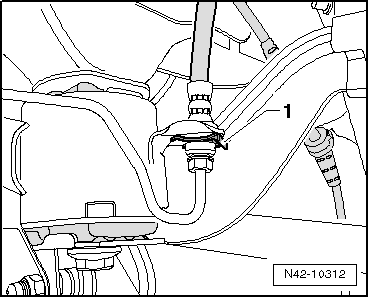
Note
Do not disconnect the brake line.
- Secure both sides of the vehicle on the hoist arms using Tensioning Straps -T10038-.

WARNING
The vehicle could slide off the hoist if it is not secured.

- Place the Engine and Gearbox Jack -VAS6931- with Universal Support Plate -VAG1359/2- below subframe and secure with strap.
- Remove hex head bolt -1 or 2- on both sides.

Note
Only the left side of the vehicle is shown in the illustration.
To secure the subframe, Locating Pins -T10096- must be screwed in one after the other on both sides of the vehicle at positions -1 and 2-.
- Location position of subframe with Locating Pins -T10096-.

Note
Locating Pins -T10096- may only be tightened to a maximum of 20 Nm, since otherwise the threads of the locating bolts will be damaged.
- Replace the bolts of the subframe one after the other on both sides using Locating Pins -T10096- and tighten them to 20 Nm.

The subframe position is now secured.
- Mark the installation location of the bonded rubber bushing on the subframe with a felt-tip pen -1-.
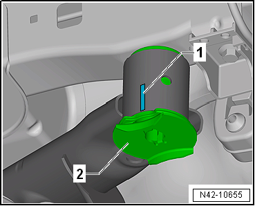
Note
Apply the mark -1- on the subframe in the middle of the recess on the bonded rubber mounting -2-.
- Use a screwdriver -2- to pry off the anti-twist mechanism -1- near the bonded rubber bushing mounting retaining lugs.
- Lower the subframe approximately 100 mm using the Engine and Gearbox Jack -VAS6931-.
- Unclip the brake line -1- from the clip -arrow- on the left side.
Note
This will destroy the clip, so it will have to be replaced.
- Use the special tools as shown.
- Hydraulic Press - Rear Subframe Bushing Tool Kit - Nut -T10263/5-
- Subframe Bushing Assembly Tool Kit - Thrust Piece -T10356/5-
- Subframe
- Subframe Bushing Assembly Tool Kit - Tube -T10356/6-, side with offset points to subframe
- Bearing Installer - Wheel Hub/Bearing Kit - Gripping Device -T10205/1-
- Hydraulic Press -VAS6178- with Bearing Installer - Wheel Hub/Bearing Kit Pressure Head -T10205/13-
- Hydraulic Press - Rear Subframe Bushing Tool Kit - Nut -T10263/5-
- Hydraulic Press - Rear Subframe Bushing Tool Kit-Threaded Rod -T10263/4-
- Pretension special tools.
- Press out the bonded rubber bushing.
Note
- When removing the bonded rubber mounting, the bearing outer race is sheared off. There is a loud crack when this happens.
- After removing the bonded rubber bushing, it must be removed from the Subframe Bushing Assembly Tool Kit - Tube -T10356/6- by tapping lightly with a hammer.
Press In the Rear Bonded Rubber Bushing
- Apply a line -1- on the vertical rib of the bonded rubber bushing to help mount.

- Apply mounting paste to the outer edge of the bonded rubber bushing.
- Insert special tools with bonded rubber bushing into subframe as illustrated.
- Hydraulic Press - Rear Subframe Bushing Tool Kit - Nut -T10263/5-
- Subframe Bushing Assembly Tool Kit - Bushing -T10356/7- - the marking -B- points to the subframe
- Subframe
- Adjust the bonded rubber bushing to the marks (the marks need to align)
- Subframe Bushing Assembly Tool Kit - Bushing -T10356/8- - the flattened sides need to fit into the cover of the bonded rubber bushing -arrows-.
- Bearing Installer - Wheel Hub/Bearing Kit - 1 -T10205/1-
- Hydraulic Press -VAS6178- with Bearing Installer - Wheel Hub/Bearing Kit Pressure Head -T10205/13-
- Hydraulic Press - Rear Subframe Bushing Tool Kit - Nut -T10263/5-
- Hydraulic Press - Rear Subframe Bushing Tool Kit - Threaded Rod -T10263/4-
- Check the position of the bonded rubber bushing and, if necessary, align and pre-tighten special tools with bonded rubber bushing.
Note
Make sure that the bonded rubber bushing is not bent when installing. Otherwise the outer ring could become damaged.
- Operate the pump to press in the bonded rubber bushing until the shoulder is positioned on the subframe "without gap".
Install in reverse order of removal. Note the following:
Tightening Specifications
| Component | Tightening Specification |
Subframe to body
|
90 Nm +90º |
 Subframe, Servicing, through 05/2012
Special tools and workshop equipment required
Tensioning Strap -T10038-
Locating Pins -T10096-
Hydraulic Press - Rear Subframe Bushing Tool Kit -T10263-
Engine and Gearbox Jack -VAS6931-
Hydraul ...
 Transverse Link, Tie Rod, AWD
Overview - Transverse Link, Tie Rod, AWD
The -arrow- points in the direction of travel.
Eccentric Bolt
Perform a vehicle alignment after loosening.
Do not turn more than 90º right or left (t ...
See More:
Volkswagen Tiguan Service and Repair Manual > Rear Suspension: Transverse Links and Tie Rods, through MY 2010, FWD
Overview - Transverse Links and Tie Rods, through MY 2010, FWD
Eccentric Bolt
For camber setting
Perform a vehicle alignment after loosening.
Nut
95 Nm
Always replace if removed
M12 x 1.5
Self-locking
Always tighten the threaded connections in curb weight position.
Eccen ...
Volkswagen Tiguan Owners Manual
Volkswagen Tiguan Service and Repair Manual
- Body exterior
- Body Interior
- General Paint Information
- Paint
- Brake System
- Suspension, Wheels, Steering
- Wheel and Tire Guide
- Towing Guide
- Wheel and Tire Guide General Information
- Communication
- Electrical Equipment General Information
- Electrical Equipment from 06/2011
- Heating, Ventilation and Air Conditioning
- Refrigerant R134a Servicing
- 6-Speed Manual Transmission 02Q, OBB, and OFB
