Volkswagen Tiguan Service and Repair Manual: Rear Axle, Removing and Installing
Special tools and workshop equipment required
- Torque Wrench 1332 40-200Nm -VAG1332-
- Engine and Gearbox Jack -VAS6931-
Removing the Subframe and its Attachments
Note
Please note that the vehicle must be resting on all four wheels for assembly work later where the multi-point bolt for the driveshaft must be loosened. Twelve-point bolt with ribs, loosening.
Twelve-point bolt without ribs, loosening.
- Remove the wheels.
- Remove the coil springs.
- Remove the rear muffler.
- Disconnect the electric connections between the rear axle and the body.
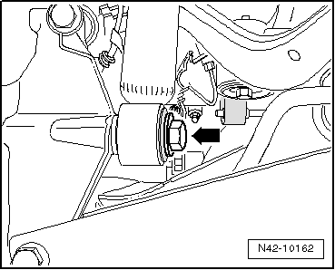
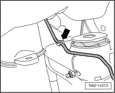
- Remove the bolt -arrow-.
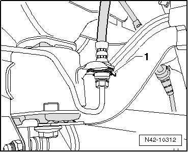
- Remove the clip -1-.

Note
Do not disconnect the brake line.
- Disconnect the parking brake connectors from the brake caliper.
- Remove the brake calipers on both sides and tie them to the body with wire.
Remove retainer -1-, pressing out inner pins of rivets -arrows A-.
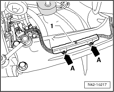
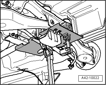
- Remove line -1- at mounting bracket -arrow A-.
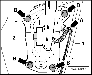
- Mark installation position of mounting bracket -2- on body.
- Remove the bolts -B arrows-.
- Disconnect Left Rear Level Control System Sensor -G76- connector.
- Check whether there is a marking (colored point) -arrows- on joint washer or final drive flange. If there is no mark, mark the position of the flexible disc and final drive flange to each other -arrows-.
- Disconnect Right Rear ABS Wheel Speed Sensor -G44- and Left Rear ABS Wheel Speed Sensor -G46- connectors.
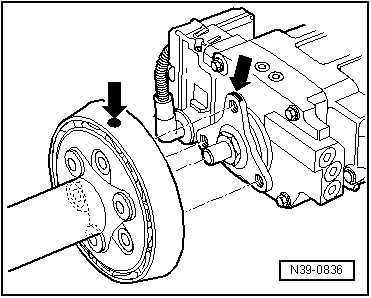
- Remove rear driveshaft tube from rear final drive with joint washer and vibration damper -arrows-.
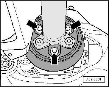
- Remove the center bracket bolts -arrows- two turns.
- Support the driveshaft -A- on the tunnel support -1- with a wood block.
- Move rear driveshaft tube as far as possible in direction of transmission.
- Disconnect connector to Haldex clutch above final drive.
- Now secure vehicle on both sides to lifting arms on hoist with Tensioning Strap -T10038-.
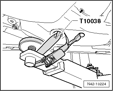
WARNING
If vehicle is not secured, it could slide off of hoist.
- Place the Engine/Gearbox Jack - VAG1383A- with Universal Support Plate -VAG1359/2- below subframe and secure with strap.
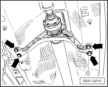
To secure the subframe, Locating Pins -T10096- must be screwed in one after the other on both sides of the vehicle at positions -1- and -2-.
Remove hex head bolt -1- or -2- on both sides.
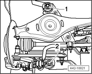
Note
Only the left side of the vehicle is shown in the illustration.
- Location position of subframe with Locating Pins -T10096-.
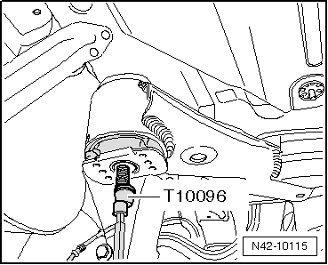
Note
Locating Pins -T10096- may only be tightened to a maximum of 20 Nm, since otherwise the threads of the locating bolts will be damaged.
- Replace the bolts of the subframe one after the other on both sides using Locating Pins -T10096- and tighten them to 20 Nm.
The subframe position is now secured.
- Carefully lower the subframe with its attachments approximately 2 cm.
- Unclip the brake line on both sides -arrow-.
Note
When doing this, the clips will be destroyed and must be replaced.
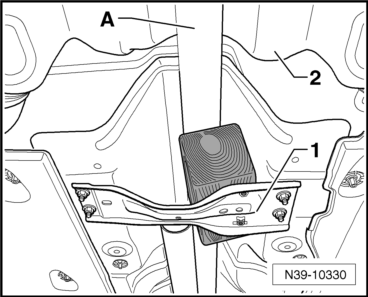
- Remove the brake line above the drive axle flange on the transmission-1- from the clips -arrows-.
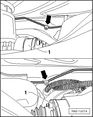
Note
When doing this, the clips will be destroyed and must be replaced.
- Carefully lower subframe with components.
Note
Make sure there is enough clearance for brake lines, electrical lines and driveshaft centering pin when lowering.
Installing the Subframe with Attachments
Install in reverse order of removal. Note the following when doing so:
Note
Replace the destroyed brake line clips on the subframe.
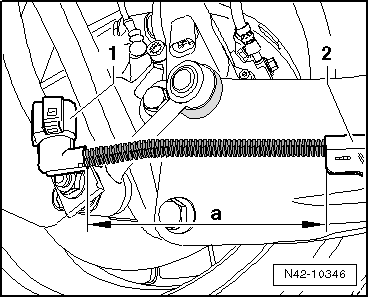
- When installing the wires for the electrical parking brake, make sure the dimension -a- between the connector -1- and the retainer -2- is exact.
Dimension -a- = 150 mm
Connect the driveshaft to the rear final drive.
Tightening Specifications
| Component | Tightening Specification |
Subframe to body
|
90 Nm +90º |
| Shock absorber to wheel bearing housing. | 180 Nm |
Mounting bracket to body
|
50 Nm + 45º |
 Subframe, Final Drive, AWD
Overview - Subframe, Final Drive, AWD
The -arrow- points in the direction of travel.
Subframe
Rear Bonded Rubber Bushing
Replacing, through 5/19/2012.
Replacing, from 05/28/2012.
Front ...
 Subframe, Servicing, through 05/2012
Special tools and workshop equipment required
Tensioning Strap -T10038-
Locating Pins -T10096-
Hydraulic Press - Rear Subframe Bushing Tool Kit -T10263-
Engine and Gearbox Jack -VAS6931-
Hydraul ...
See More:
Volkswagen Tiguan Owners Manual > Rear Assist with dynamic orientation lines: Operation
Fig. 139 In the rear hatch: Location
of the Rear Assist camera.
Fig. 140 Display of the Rear Assist:
Mode 1 activated.
Read and follow the introductory information and
safety information first⇒Introduction
to the subject Function buttons on the screen ⇒ Fig. 140 :
Display the m ...
Volkswagen Tiguan Owners Manual
Volkswagen Tiguan Service and Repair Manual
- Body exterior
- Body Interior
- General Paint Information
- Paint
- Brake System
- Suspension, Wheels, Steering
- Wheel and Tire Guide
- Towing Guide
- Wheel and Tire Guide General Information
- Communication
- Electrical Equipment General Information
- Electrical Equipment from 06/2011
- Heating, Ventilation and Air Conditioning
- Refrigerant R134a Servicing
- 6-Speed Manual Transmission 02Q, OBB, and OFB
