Volkswagen Tiguan Service and Repair Manual: Subframe, through MY 2010, FWD
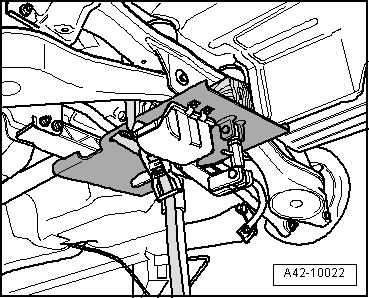
Overview - Subframe, through MY 2010, FWD
The -arrow- points in the direction of travel.
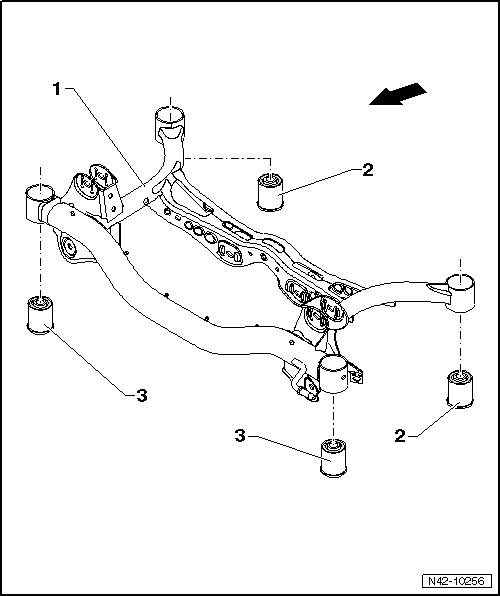
- Subframe
- Rear Bonded Rubber Bushing
- Replacing.
- Front Bonded Rubber Bushing
- Replacing.
Rear Axle, Removing and Installing
Special tools and workshop equipment required
- Torque Wrench 1332 40-200Nm -VAG1332-
- Engine and Gearbox Jack -VAS6931-
Removing the Subframe and its Attachments
- Remove the wheels.
- Remove the coil springs.
- Disconnect the electric connections between the rear axle and the body.
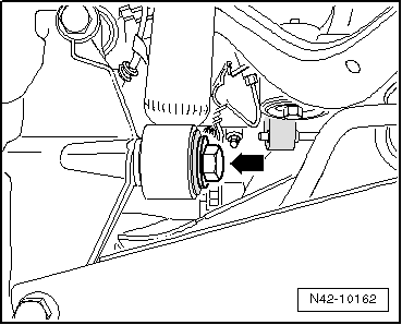
- Remove the bolt -arrow-.
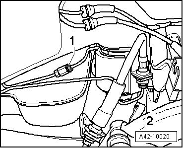
- Disconnect brake lines -1 and 2-.
- Disconnect the parking brake connectors from the brake caliper.
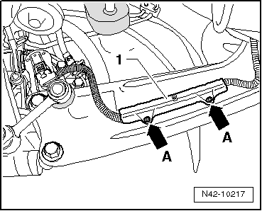
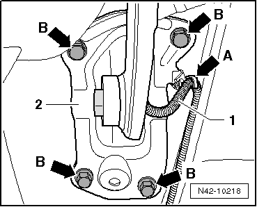
- Remove retainer -1-, pressing out inner pins of rivets -arrows A-.
- Remove line -1- at mounting bracket -arrow A-.
- Mark installation position of mounting bracket -2- on body.
- Remove the bolts -B arrows-.
- Disconnect Left Rear Level Control System Sensor -G76- connector.
- Now secure vehicle on both sides to lifting arms on hoist with Tensioning Strap -T10038-.

WARNING
If vehicle is not secured, it could slide off of hoist.
- Place the Engine/Gearbox Jack -VAG1383A- with Universal Support Plate -VAG1359/2- below subframe and secure with strap.

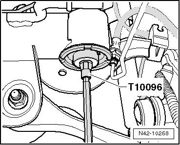
- Remove hex head bolt -1 or 2- on both sides.
Note
Only the left side of the vehicle is shown in the illustration.
To secure the subframe, Locating Pins -T10096- must be screwed in one after the other on both sides of the vehicle at positions -1 and 2-.
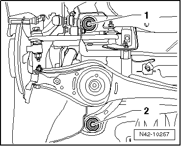
- Location position of subframe with Locating Pins -T10096-.
Note
Locating Pins -T10096- may only be tightened to a maximum of 20 Nm, otherwise the threads of the locating bolts will be damaged.
- Replace the bolts of the subframe one after the other on both sides using Locating Pins -T10096- and tighten them to 20 Nm.
The subframe position is now secured.
- Carefully lower subframe with components.

Note
When lowering, ensure the brake lines and wires have sufficient clearance.
Installing the Subframe with Attachments
Install in reverse order of removal. Note the following when doing so:
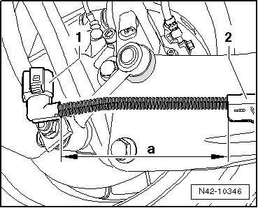
- When installing the wires for the electrical parking brake, make sure dimension -a- between the connector -1- and the retainer -2- is exact.
Dimension -a- = 150 mm
- Bleed the brake system.
Tightening Specifications
| Component | Tightening Specification |
Subframe to body
|
90 Nm + 90º |
| Shock absorber to wheel bearing housing. | 180 Nm |
Mounting bracket to body
|
50 Nm + 45º |
Subframe, Servicing
Special tools and workshop equipment required
- Tensioning Strap -T10038-
- Locating Pins -T10096-
- Engine and Gearbox Jack -VAS6931-
- Hydraulic Press -VAS6178- with Bearing Installer - Wheel Hub/Bearing Kit- Pressure Head -T10205/13-
- Pneumatic/Hydraulic Foot Pump -VAS6179-
- Subframe Bushing Assembly Tool Kit -T10356-
- Remove rear wheels.
- Remove the coil springs.
- Disconnect the electric connections between the rear axle and the body.
- Remove the stabilizer bar.
- Now secure vehicle on both sides to lifting arms on hoist with Tensioning Strap -T10038-.
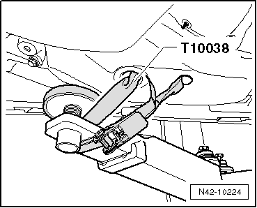
WARNING
If vehicle is not secured, it could slide off of hoist.
- Place the Engine and Gearbox Jack -VAS6931- with Universal Support Plate -VAG1359/2- below subframe and secure with strap.
- Remove hex head bolt -1 or 2- on both sides.
Note
Only the left side of the vehicle is shown in the illustration.
To secure the subframe, Locating Pins -T10096- must be screwed in one after the other on both sides of the vehicle at positions -1 and 2-.

- Location position of subframe with Locating Pins -T10096-.
Note
Locating Pins -T10096- may only be tightened to a maximum of 20 Nm, since otherwise the threads of the locating bolts will be damaged.
- Replace the bolts of the subframe one after the other on both sides using Locating Pins -T10096- and tighten them to 20 Nm.
The subframe position is now secured.
- Lower subframe approximately 10 cm using Engine and Gearbox Jack -VAS6931-.
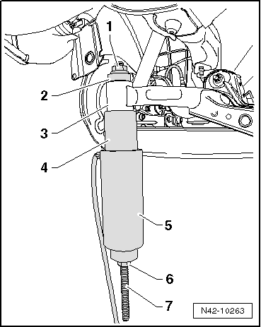
Removing Front Bonded Rubber Bushing
- Install special tools as depicted in the illustration.
- Hydraulic Press - Rear Subframe Bushing Tool Kit-Nut -T10263/5-
- Subframe Bushing Assembly Tool Kit-Press Piece -T10356/1-
- Subframe
- Subframe Bushing Assembly Tool Kit-Tube -T10356/2-
- Hydraulic Press -VAS6178- with Bearing Installer - Wheel Hub/Bearing Kit- Pressure Head -T10205/13-
- Hydraulic Press - Rear Subframe Bushing Tool Kit-Nut -T10263/5-
- Hydraulic Press - Rear Subframe Bushing Tool Kit-Spindle -T10263/4-
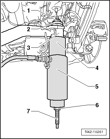
- Pretension special tools.
- Pull out bonded rubber bushing by operating pump.
Note
- The bearing outer race is sheared off when the bonded rubber bushing is removed. There is a loud crack when this happens.
- After removing the bonded rubber bushing, it must be removed from the Tube -T10356/2- by tapping lightly with a hammer.
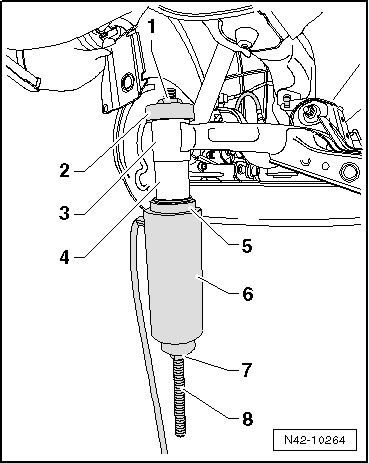
Installing Front Bonded Rubber Bushing
- Insert special tools with bonded rubber bushing into subframe as illustrated.
- Hydraulic Press - Rear Subframe Bushing Tool Kit-Nut -T10263/5-
- Subframe Bushing Assembly Tool Kit - Guide Piece -T10356/3- with side A toward subframe
- Subframe
- Bonded rubber bushing
- Subframe Bushing Assembly Tool Kit - Press Piece -T10356/4- with side A toward bonded rubber bushing
- Subframe Bushing Assembly Tool Kit-Tube -T10356/2-
- Hydraulic Press -VAS6178- with Bearing Installer - Wheel Hub/Bearing Kit- Pressure Head -T10205/13-
- Hydraulic Press - Rear Subframe Bushing Tool Kit-Nut -T10263/5-
- Hydraulic Press - Rear Subframe Bushing Tool Kit-Spindle -T10263/4-
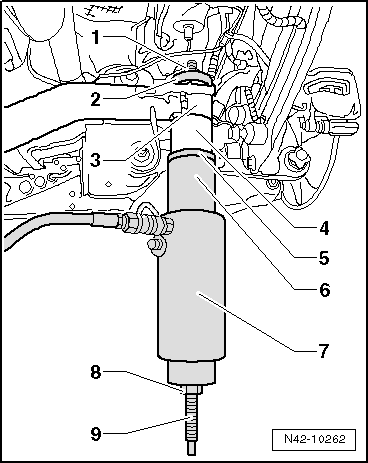
- Pretension special tool with bonded rubber bushing.
- Carefully insert bonded rubber bushing by operating pump until collar lies on subframe "without a gap".
Pulling Out Rear Bonded Rubber Bushing
- Install special tools as depicted in the illustration.
- Hydraulic Press - Rear Subframe Bushing Tool Kit-Nut -T10263/5-
- Subframe Bushing Assembly Tool Kit - Thrust Piece -T10356/5-
- Subframe
- Subframe Bushing Assembly Tool Kit - Tube -T10356/6-
- Hydraulic Press -VAS6178- with Bearing Installer - Wheel Hub/Bearing Kit- Pressure Head -T10205/13-
- Hydraulic Press - Rear Subframe Bushing Tool Kit-Nut -T10263/5-
- Hydraulic Press - Rear Subframe Bushing Tool Kit-Spindle -T10263/4-
- Pretension special tools.
- Pull out bonded rubber bushing by operating pump.
Note
- The bearing outer race is sheared off when the bonded rubber bushing is removed. There is a loud crack when this happens.
- After removing the bonded rubber bushing, it must be removed from the Tube -T10356/2- by tapping lightly with a hammer.
Pulling In Rear Bonded Rubber Bushing
- Insert special tools with bonded rubber bushing into subframe as illustrated.
- Hydraulic Press - Rear Subframe Bushing Tool Kit-Nut -T10263/5-
- Hydraulic Press - Rear Subframe Bushing Tool Kit-Guide Piece -T10356/3- with side B toward subframe
- Subframe
- Bonded rubber bushing
- Subframe Bushing Assembly Tool Kit - Press Piece -T10356/4- with side B toward bonded rubber bushing
- Hydraulic Press -VAS6178- with Bearing Installer - Wheel Hub/Bearing Kit- Pressure Head -T10205/13-
- Hydraulic Press - Rear Subframe Bushing Tool Kit-Nut -T10263/5-
- Hydraulic Press - Rear Subframe Bushing Tool Kit-Spindle -T10263/4-
- Pretension special tool with bonded rubber bushing.
- Carefully insert bonded rubber bushing by operating pump until collar lies on subframe "without a gap".
Install in reverse order of removal. Note the following when doing so:
- Bleed the brake system.
Tightening Specifications
| Component | Tightening Specification |
Subframe to body
|
90 Nm + 90º |
 Rear Suspension, FWD, Servicing
Overview - Rear Axle
Note
Welding and straightening work on supporting or wheel carrying
components of the suspension is not permitted.
Always replace self-locking nuts.
Always replace corroded ...
 Transverse Links and Tie Rods, through MY 2010, FWD
Overview - Transverse Links and Tie Rods, through MY 2010, FWD
Eccentric Bolt
For camber setting
Perform a vehicle alignment after loosening.
Nut
95 Nm
Always replace if removed
M1 ...
See More:
Volkswagen Tiguan Owners Manual > Vehicle tool kit: Introduction to the subject
In this chapter you will find information on the following subjects:⇒ Storage
⇒ Contents ⇒ Folding chocks
When securing the vehicle after a breakdown, always obey all applicable legal
requirements.
More information:
Trailer towing ⇒ Trailer towing
Preparations for w ...
Volkswagen Tiguan Owners Manual
Volkswagen Tiguan Service and Repair Manual
- Body exterior
- Body Interior
- General Paint Information
- Paint
- Brake System
- Suspension, Wheels, Steering
- Wheel and Tire Guide
- Towing Guide
- Wheel and Tire Guide General Information
- Communication
- Electrical Equipment General Information
- Electrical Equipment from 06/2011
- Heating, Ventilation and Air Conditioning
- Refrigerant R134a Servicing
- 6-Speed Manual Transmission 02Q, OBB, and OFB
