Volkswagen Tiguan Service and Repair Manual: Antilock Brake System
ABS General Information
The ABS brake system is divided diagonally. The brake booster operates pneumatically via the vacuum brake booster.Vehicles with ABS do not have a mechanical brake pressure regulator. A specially coordinated software program in the control module determines brake pressure allocation at the rear axle.
ABS malfunctions do not affect the brake system and the booster. The conventional brake system remains operative even without ABS. A change in braking behavior must be anticipated. When the ABS indicator lamp comes on, the rear wheels may lock prematurely when braking!ABS Layout
- Hydraulic unit and control module
- Brake booster
The control module and hydraulic unit form one component. Separation is not possible. The hydraulic pump must also not be separated from the hydraulic unit.
ABS Repair Information
- Before carrying out repair work on the ABS, determine the cause of damage as well as the control module code using "Guided Fault Finding".
"Guided Fault Finding" is performed using the Vehicle Diagnostic Tester.
- Disconnect the battery ground cable when the ignition is switched off.
- Before welding with an electric welding tool.
- When handling brake fluid, observe the relevant safety precautions and notes.
- After finishing any work that required opening the brake system, bleed the brake system using the Brake Charger/Bleeder Unit -VAS5234-.
- During the final road test, make sure a controlled braking maneuver is performed at least one time (pulsing must be felt in brake pedal).
- Absolute cleanliness is required when working on the ABS. Do not use any products which contain mineral oil, such as oils, greases etc.
- Thoroughly clean all connection points and their surrounding areas before loosening. However, do not use aggressive cleaning agents such as brake cleaner, gasoline, thinners or similar compounds.
- Place the removed parts on a clean surface and cover them.
- After disconnecting the control module from the hydraulic unit, use the valve body transport protection.
- Carefully cover or seal opened components if the repair is not performed immediately. Use sealing plugs from the Repair Kit -1H0 698 311 A-
- Only use lint-free cloths.
- Remove the replacement parts from their packaging just prior to installing them.
- Only use parts in their original packaging.
- If the system is open, do not work with compressed air and do not move the vehicle.
- When painting, electronic control module can be exposed to a maximum temperature of 95 ºC (203 ºF) only briefly, and to a maximum of 85 ºC (185 ºF) for longer periods (approximately two hours).
- Make sure that brake fluid cannot get into the connectors.
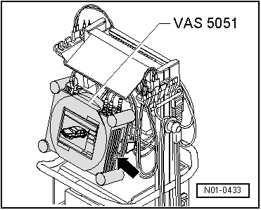
Vehicle Diagnostic Tester-, Connecting and Selecting Functions
Special tools and workshop equipment required
- Vehicle Diagnostic Tester
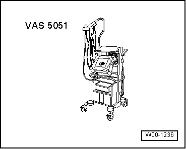
- Diagnostic Cable -VAS5051/1- or Diagnostic Cable -VAS5051/3-
WARNING
- During a test drive, the testing and measuring equipment must always be secured on the back seat.
- These devices may be operated only by a passenger during a test drive.
- Connect the Diagnostic Cable -VAS5051/1- or Diagnostic Cable -VAS5051/3- or - VAS5051/3- to the Data Link Connector.
- Switch on the tester -arrow-.
The tester is operational when it displays a picture of a car.
- Switch the ignition on.
- Touch Guided Fault Finding.
- Select in succession:
- Brand
- Type
- Model year
- Version
- Engine Codes
- Confirm the entered data.
Wait until the tester has checked all control modules in the vehicle.
- Press GO TO and select "function/component selection".
- Select on the display "Running gear"
- Select on the display "Brake system"
- Select "01 - On Board Diagnostic Capable System" in the display.
Either
- Select "ABS..." on the display.
Or
- Select on display "Electric Park/Handbrake"
- Select "function" indicated on display.
Now, all possible functions of the ABS installed in the vehicle will be displayed.
- Select the desired function on display.
Electrical and Electronic Components and Component Locations
ABS TRW (ABS/EDL/ASR/ESP)
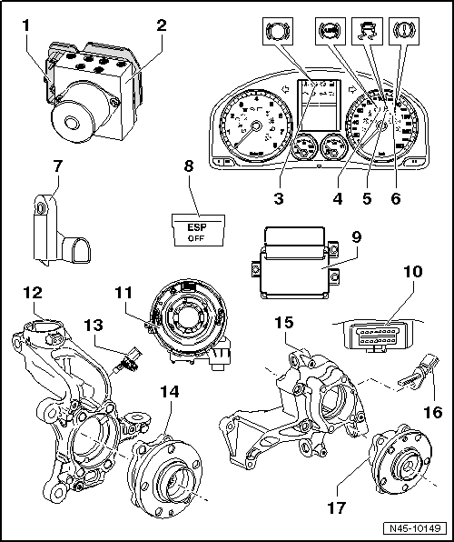
- ABS Control Module -J104-
- Component location: On the hydraulic unit in the left of the engine compartment under the battery.
- Do not disconnect the connector before successfully completing OBD. Switch off the ignition before disconnecting the connector.
- Must not be separated from the ABS Hydraulic Unit -N55-
- Removing and installing.
- ABS Hydraulic Unit -N55-
- Component location: in the left of the engine compartment under the battery.
The hydraulic unit consists of the components:
- Brake Pressure Sensor 1 -G201-
- ABS Hydraulic Pump -V64-
- Valve block (contains intake and exhaust valves)
- The ABS Hydraulic Pump -V64- and valve block must not be separated from one another.
- Must not be separated from the ABS Control Module -J104-
- Removing and installing.
- Brake Pad Wear Indicator Lamp -K32-
- Component location: in the instrument cluster
- ABS Indicator Lamp -K47-
- Component location: in the instrument cluster
- ASR/ESP Indicator Lamp -K155-
- Component location: in the instrument cluster
- Brake System Indicator Lamp -K118-
- Component location: in the instrument cluster
- Brake Lamp Switch -F-
- Component location: on the brake master cylinder
- Removing and installing.
- ASR/ESP Button -E256-
- Component location: inside the center console
- ESP Sensor Unit -G419- and Electromechanical Parking Brake Control
Module -J540-
- Component location: under the center console
- Combined Transverse Acceleration Sensor -G200-, Rotation Rate Sensor -G202- and Longitudinal Acceleration Sensor -G251-
- Installed together in one housing with the Electromechanical Parking Brake Control Module -J540-.
- Removing and installing.
- Data Link Connector
- Component location: driver side footwell cover
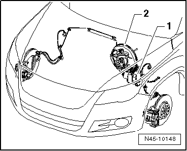
- Steering Angle Sensor -G85-
- Component location: On steering column between steering wheel and steering column switch
- Removing and installing.
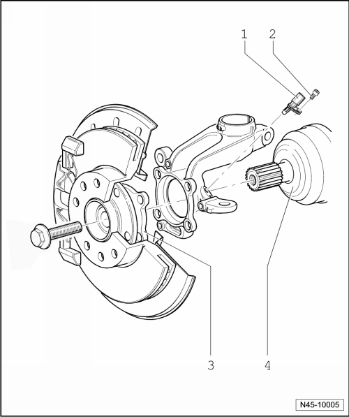
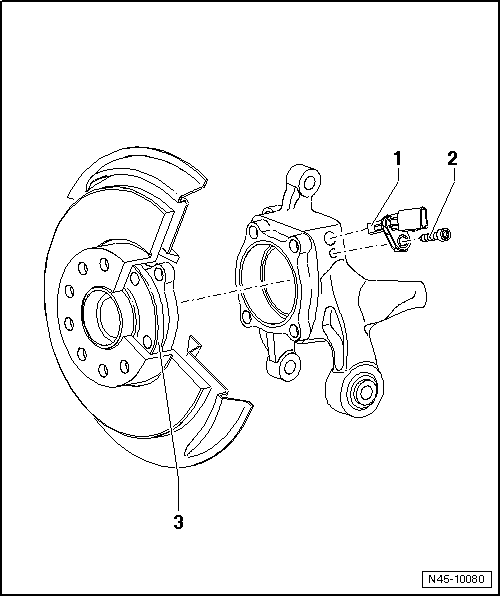
- Wheel Bearing Housing
- Right and Left Front ABS Wheel Speed Sensor -G45-/-G47-
- Removing and installing.
- Wheel Hub with Wheel Bearing
- The ABS sensor ring is installed in the wheel bearing
- Wheel Bearing Housing
AWD illustration
- Right and Left Rear ABS Wheel Speed Sensor-G44-/-G46-
- Removing and installing (FWD).
- Removing and installing (AWD).
- Wheel Hub with Wheel Bearing
AWD illustration
- The ABS sensor ring is installed in the wheel bearing
Hydraulic Unit
ABS TRW (ABS/EDL/ASR/ESP)
Overview - Hydraulic Unit
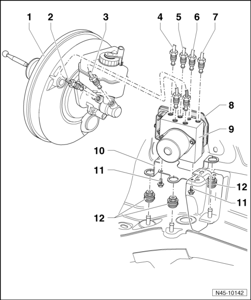
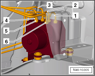
- Brake Booster
- Removing and installing.
- Brake Line
- Brake master cylinder/primary piston circuit to hydraulic unit
- Identification: 6.5 mm diameter and tube fitting with a M12 x 1 long thread
- Labeled on hydraulic unit with "HZ1"
- Brake Line
- Brake master cylinder/secondary piston circuit to hydraulic unit
- Identification: 6.5 mm diameter and tube fitting with a M12 x 1 long thread
- Labeled on hydraulic unit with "HZ2"
- Brake Line
- To the right front brake caliper
- Identification: 5.25 mm diameter and tube fitting with a M10 x 1 thread
- Labeled on hydraulic unit with "VR"
- Brake Line
- To the left rear brake caliper
- Identification: 5.25 mm diameter and tube fitting with a M12 x 1 short thread
- Labeled on hydraulic unit with "HL"
- Brake Line
- To the right rear brake caliper
- Identification: 5.25 mm diameter and tube fitting with a M10 x 1 thread
- Labeled on hydraulic unit with "HR"
- Brake Line
- To the left front brake caliper
- Identification: 5.25 mm diameter and tube fitting with a M12 x 1 short thread
- Marked on hydraulic unit with "VL"
- ABS Control Module -J104-
It is not possible to separate the control module and hydraulic unit.
- Removing.
- Installing.
- ABS Hydraulic Unit -N55-
It is not possible to separate the control module and hydraulic unit.
- Removing.
- Installing.
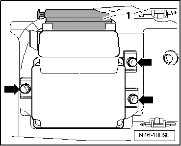
- Bracket
- TORX Socket Bolt
- 8 Nm
- Rubber Bushing
Control Module and Hydraulic Unit, Removing
Special tools and workshop equipment required
- Torque Wrench 1331 5-50Nm -VAG1331-
- Torque Wrench 1410 -VAG1410-
- Brake Pedal Actuator -VAG1869/2-.
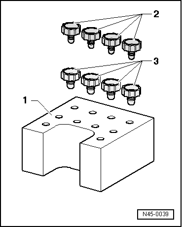
Sealing Plugs from the Repair Kit -1H0 698 311 A-
- Transportation protection for valve body (foam)
- M10 plug
- M12 plug
Removing
Component Location:
The control module is bolted to the hydraulic unit and is located at the left of the engine compartment under the battery carrier.
WARNING
Do not bend the brake lines near the hydraulic unit.
- Read and note the present control module code.
- On vehicles with a coded radio, note the code and if necessary retrieve it.
- Disconnect the battery.
- Remove the air filter housing.
- Remove battery and the battery carrier.
- Open the cable guide, remove both wiring harnesses and move them to the side.
- Remove the wiring guide from the console.
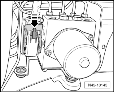
- Press the red lock washer down in the direction of -arrow-.
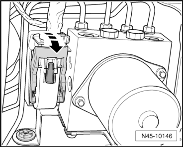
- Release and remove the connector from the control module in the direction of -arrow-.
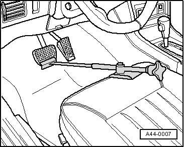
- Insert the Brake Pedal Actuator -VAG1869/2-.
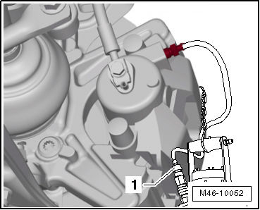
- Attach the bleeder bottle bleed hose -1- to the left front brake caliper bleed valve.
- Open the bleeder valve.
- Attach the bleeder bottle bleed hose -1- to the left rear brake caliper bleed valve.
- Open the bleeder valve.
- Operate the brake pedal at least 60 mm using the Brake Pedal Actuator -VAG1869/2-.
- Close the left front and left rear bleeder valves.
- Do not remove the Brake Pedal Actuator -VAG1869/2-.
- Place enough lint-free cloths under the control module and hydraulic unit.
Make sure that no brake fluid gets into the contacts.
- First mark both brake lines from the brake master cylinder and remove them.
- Immediately seal off the brake lines and the threaded holes with the plugs from Repair Kit -1H0 698 311 A-.
- Mark, remove and seal off the remaining brake lines (brake calipers).
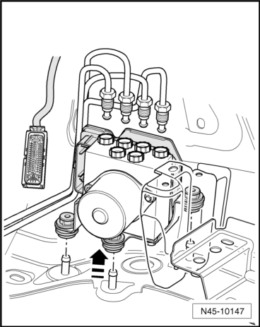
- Pull the hydraulic unit with the control module upward out of the shock absorbers -arrow-.
Control Module and Hydraulic Unit, Installing
Note
- Only remove the plugs on the new hydraulic unit if the corresponding brake line is installed.
- If the plugs are removed too early from the hydraulic unit, brake fluid can escape and the unit may not be sufficiently filled or adequately bled.
- When installing the hydraulic unit, make sure the rubber bushing is not pushed out of the bracket. The rubber bushing must lie on the longitudinal member cover plate.
- Install in reverse order of removal.
Fastening Sequence of Brake Lines
- ABS Hydraulic Unit -N55- to the left front brake caliper
- Identification at ABS Hydraulic Unit -N55- -VL-
- ABS Hydraulic Unit -N55- to the right rear brake caliper
- Identification at ABS Hydraulic Unit -N55- -HR-
- ABS Hydraulic Unit -N55- to the left rear brake caliper
- Identification at ABS Hydraulic Unit -N55- -HL-
- ABS Hydraulic Unit -N55- to the right front brake caliper
- Identification at ABS Hydraulic Unit -N55- -VR-
- ABS Hydraulic Unit -N55- to the master brake cylinder secondary piston
circuit
- Identification at ABS Hydraulic Unit -N55- -HZ2-
- ABS Hydraulic Unit -N55- to the master brake cylinder primary piston
circuit
- Identification at ABS Hydraulic Unit -N55- -HZ1-
- Remove the Brake Pedal Actuator -VAG1869/2-.
- Bleed the brake system.
- Code the radio.
- Code the ABS Control Module -J104- using the Vehicle Diagnostic Tester in "Guided Fault Finding".
Performs the basic setting of the Steering Angle Sensor -G85-, the Transverse Acceleration Sensor -G200-, Longitudinal Acceleration Sensor -G251- and the Brake Pressure Sensor 1 -G201-.
Tightening Specifications
| Component | Tightening Specification |
| Bolt for ABS Hydraulic Unit -N55- to bracket | 8 Nm |
| Brake lines to ABS Hydraulic Unit -N55- | |
| M10 x 1 Thread | 14 Nm |
| M12 x 1 Thread | 14 Nm |
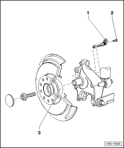
ABS System Components on Front and Rear Axles, Removing and Installing
ABS System Components, Front Axle, Removing and Installing
- ABS Wheel Speed Sensor
- Before inserting the speed sensor, clean the inside of the hole and coat it with hot bolt paste G 052 112 A3.
- Removing and installing.
- Hex Socket Bolt
- 8 Nm
- Wheel Hub with Wheel Bearing
- The ABS sensor ring is installed in the wheel bearing
- Drive
Front Axle Speed Sensor, Removing and Installing
Removing
- Raise the vehicle.
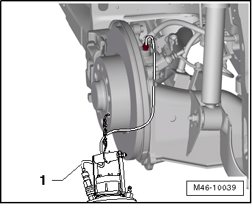
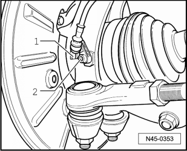
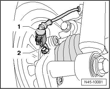
- Separate the speed sensor and the speed sensor wiring connector -1-.
- Remove the bolt -2- from wheel bearing housing.
- Remove the ABS speed sensor from wheel bearing housing.
Installing
- Before inserting the speed sensor, clean the hole inner surface and coat speed sensor all-round with hot bolt paste G 052 112 A3.
- Before inserting the speed sensor, clean the hole inner surface and coat speed sensor all-round with hot bolt paste G 052 112 A3.
- Connect the speed sensor to speed sensor wiring.
ABS Components on Rear Axle, Removing and Installing, FWD
- ABS Wheel Speed Sensor
- Before inserting the speed sensor, clean the inside of the hole and coat it with hot bolt paste G 052 112 A3.
- Removing and installing.
- Hex Socket Bolt
- 8 Nm
- Wheel Hub with Wheel Bearing
- The ABS sensor ring is installed in the wheel bearing
Speed Sensor on Rear Axle, Removing and Installing
Removing
- Raise the vehicle.
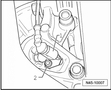
- Separate the speed sensor and the speed sensor wiring connector -1-.
- Remove the bolt -2- from wheel bearing housing.
- Remove the ABS speed sensor from wheel bearing housing.
Installing
- Before inserting the speed sensor, clean the hole inner surface and coat speed sensor all-round with hot bolt paste G 052 112 A3.
- Insert the speed sensor into the hole in the wheel bearing housing and tighten the bolt to 8 Nm.
- Connect the speed sensor to speed sensor wiring.
ABS Components on Rear Axle, Removing and Installing, AWD
- ABS Wheel Speed Sensor
- Before inserting the speed sensor, clean the inside of the hole and coat it with hot bolt paste G 052 112 A3.
- Removing and installing.
- Hex Socket Bolt
- 8 Nm
- Wheel Hub with Wheel Bearing
- The ABS sensor ring is installed in the wheel bearing
Speed Sensor on Rear Axle, Removing and Installing
Removing
- Raise the vehicle.
- Separate the speed sensor and the speed sensor wiring connector -1-.
- Remove the bolt -2- from wheel bearing housing.
- Remove the ABS speed sensor from wheel bearing housing.
Installing
- Before inserting the speed sensor, clean the hole inner surface and coat speed sensor all-round with hot bolt paste G 052 112 A3.
- Insert the speed sensor into the hole in the wheel bearing housing and tighten the bolt to 8 Nm.
- Connect the speed sensor to speed sensor wiring.
ESP System Components, Removing and Installing
ESP Sensor Unit -G419-, Removing and Installing
The Transverse Acceleration Sensor -G200-, the Rotation Rate Sensor -G202- and the Longitudinal Acceleration Sensor -G251- are installed in a housing together with the Electromechanical Parking Brake Control Module -J540- under the center console.
After replacing the ESP Sensor Unit -G419- with the Electro-Mechanical Parking Brake Control Module -J540-, the ABS Control Module -J104- must be coded and a basic setting of the "brake system" (Electro-Mechanical Parking Brake) must be performed.
WARNING
Excessive shaking (for example, dropping, impact) may damage the ESP Sensor Unit -G419-. The ESP Sensor Unit -G419- must then no longer be used.
Removing
- Remove the center console.
- Disconnect the connector -1- from the ESP Sensor Unit -G419-.
- Remove the three nuts -arrows-.
- Remove the ESP Sensor Unit -G419-.
Installing
- Install in reverse order of removal.
When installing the ESP Sensor Unit -G419-, make sure it is seated correctly in its mounting without tension.
Note
Do not use the nuts to forcibly position the ESP Sensor Unit -G419-.
- Tighten the nuts to 9 Nm.
- Code the ABS Control Module -J104- using the Vehicle Diagnostic Tester in "Guided Fault Finding".
While doing so, a basic setting for the Steering Angle Sensor -G85-, Transverse Acceleration Sensor -G200-, Brake Pressure Sensor 1 -G201- and Longitudinal Acceleration Sensor -G251- must be performed.
- Perform basic a setting for the "brake system" (Electro-Mechanical Parking Brake).
Connect the -Vehicle Diagnostic Tester- and select the function.
Steering Angle Sensor -G85-, Removing and Installing
The Steering Angle Sensor -G85- is installed between the steering wheel and steering column switch.
Removing and Installing
- Afterwards, the basic setting of Steering Angle Sensor -G85- must be performed.
Connect the -Vehicle Diagnostic Tester- and select the function.
Special Tools
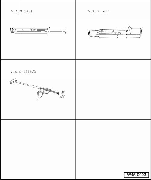
Special tools and workshop equipment required
- Torque Wrench 1331 5-50Nm -VAG1331-
- Torque Wrench 1410 -VAG1410-
- Brake Pedal Actuator -VAG1869/2-.
- Vehicle Diagnostic Tester
- Diagnostic Cable -VAS5051/1- or Diagnostic Cable -VAS5051/3-
 General, Technical data
Brake PR Number, Allocating
Front Brakes
Engine
PR Number
Front
Brakes
2.0L - 147 kW FSI
1ZD
FN3 (16")
Rear Brakes
Engine
PR Number
Rear
Brakes
2.0L - 147 kW ...

See More:
Volkswagen Tiguan Service and Repair Manual > Tires, Mounting: Tires, Dismounting
Remove the valve insert.
Note
If equipped handle the glued-on wheel trim carefully. Surface slightly
scratched.
Replace the damaged rim wheel trim.
Place the press-off blade -1- over the tire
valve -arrow- and maximum 2 cm away from rim
flange.
Remove the balance weight and any dirt ...
Volkswagen Tiguan Owners Manual
Volkswagen Tiguan Service and Repair Manual
- Body exterior
- Body Interior
- General Paint Information
- Paint
- Brake System
- Suspension, Wheels, Steering
- Wheel and Tire Guide
- Towing Guide
- Wheel and Tire Guide General Information
- Communication
- Electrical Equipment General Information
- Electrical Equipment from 06/2011
- Heating, Ventilation and Air Conditioning
- Refrigerant R134a Servicing
- 6-Speed Manual Transmission 02Q, OBB, and OFB
