Volkswagen Tiguan Service and Repair Manual: Steering Column Combination Switch -E595-
General Information
Depending on vehicle equipment, the Steering Column Combination Switch -E595- consists of the following components and cannot be disassembled:
- Turn Signal Switch -E2-
- Windshield Wiper Switch -E-
- Cruise Control Switch -E45-
The procedure for removing and installing the steering column combination switch differs depending on the manufacturer.
- Steering Column Combination Switch -E595-, Removing and Installing, Valeo.
- Steering Column Combination Switch -E595-, Removing and Installing, Kostal.
Steering Column Combination Switch -E595-, Removing and Installing, Valeo
Caution
Always follow the sequence when removing and installing steering column switch components.
WARNING
Before working on electronic system and removing the steering wheel the following conditions must be met:
The technician must discharge static electricity. This is accomplished by touching grounded metal like, for example, water pipes, heating pipes, metal carriers or a heater pipe.
If this note is ignored it can result in failure of the control modules during later operation.
- Remove the battery ground cable.
- Wheels must be located in straight ahead position.
If this note is ignored, it can result in failure of the airbag system during later operation.
Caution
If the universal joint is separated from the steering gear, or the Steering Angle Sensor -G85- is removed, do not perform the following tasks:
- Connecting the battery
- Turning on the ignition
- Turning the steering gear.
- Turning the steering column.
These points must be followed otherwise, it can lead to irreparable damage.
Removing
- Remove the steering wheel.
- Remove the steering column trim panel.
- Remove the Steering Column Electronics Control Module -J527-.
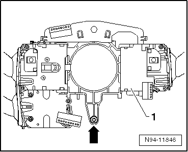
- Open the three latching mechanisms -arrows- and remove the complete Steering Column Combination Switch -E595--2- straight backward from the steering column switch mount.
Installing
- Slide the Steering Column Combination Switch -E595- straight onto the guides on the steering column switch mount until it locks in place.
- Install all components accordingly in the reverse order.
Steering Column Combination Switch -E595-, Removing and Installing, Kostal
Caution
Always follow the sequence when removing and installing steering column switch components.
WARNING
Before working on electronic system and removing the steering wheel the following conditions must be met:
The technician must discharge static electricity. This is accomplished by touching grounded metal like, for example, water pipes, heating pipes, metal carriers or a heater pipe.
If this note is ignored it can result in failure of the control modules during later operation.
- Remove the battery ground cable.
- Wheels must be located in straight ahead position.
If this note is ignored, it can result in failure of the airbag system during later operation.
Removing
- Remove the steering wheel.
- Remove the steering column trim panel.
- Remove the Steering Column Electronics Control Module -J527-.
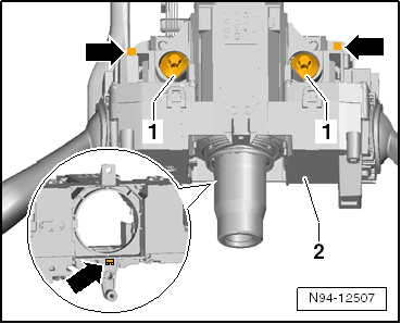
- Remove the screw -arrow- and remove the entire Steering Column Combination Switch -E595--1- straight back from the steering column switch mount.
Installing
- Slide the Steering Column Combination Switch -E595- straight onto the guides on the steering column switch mount.
- Install the screw -arrow- and tighten to 1.5 Nm.
- Install all components accordingly in the reverse order.
 Steering Column Electronics Control Module -J527-
General Information
The Steering Column Electronics Control Module -J527- includes the following
components and cannot be disassembled:
Airbag Spiral Spring/Return Spring with Slip Ring -F138-
Ste ...
 Steering Column Switch Mount
General Information
WARNING
Before working on electronic system and removing the steering wheel the
following conditions must be met:
The technician must discharge static electricity. This is accompl ...
See More:
Volkswagen Tiguan Service and Repair Manual > Passenger Protection, Airbags, Seat Belts: Crash Sensors
Tools
Required Special Tools and Testing Equipment
Pop Rivet Nut Pliers -VAS5072A-
Torque Wrench 1783 - 2-10Nm -VAG1783-
Driver Front Airbag Crash Sensor -G283-, Removing and Installing
Removing
Note
The Driver Front Airbag Crash Sensor -G283- in installed in the engine
compartment above the l ...
Volkswagen Tiguan Owners Manual
Volkswagen Tiguan Service and Repair Manual
- Body exterior
- Body Interior
- General Paint Information
- Paint
- Brake System
- Suspension, Wheels, Steering
- Wheel and Tire Guide
- Towing Guide
- Wheel and Tire Guide General Information
- Communication
- Electrical Equipment General Information
- Electrical Equipment from 06/2011
- Heating, Ventilation and Air Conditioning
- Refrigerant R134a Servicing
- 6-Speed Manual Transmission 02Q, OBB, and OFB
