Volkswagen Tiguan Service and Repair Manual: Cellular Telephone and Two-Way Radio Operation
General Information
Cellular Telephones and Two-Way Radios Cannot Be Operated within the Vehicle without A Separate External Antenna
- Radio remote controls (for example, a garage door opener) and wireless units (for example, a keyboard or PC mouse) may only be used in the vehicle if the transmitted output is a maximum of 100mW.
- Installation of "e-marked units" is only permitted (Europe only).
- Cellular telephones or other retrofitted two-way units (business equipment) must have a "CE mark" (Europe only).
- Follow the operating and installation instructions provided by the manufacturer of the cellular telephones, radio-based devices, and antennas.
- The device can only reach its operational range with an exterior antenna.
- When telephone and two-way radio systems are installed correctly there is no danger to safety system such as ABS or airbags. Requiring, however, that there has been no interference in their installations. Parallel wiring to such systems must be avoided.
- Excessively high electromagnetic fields can arise if cellular telephones and two-way radios, with or without an incorrectly installed exterior antenna, are used.
In such a case, damage to health and interference with vehicle electronics cannot be ruled out.
Requirements for Installing and Operating Radios/Telephones with a Transmitted Output Above 10 Watts for Radio Services Listed in the Table:
- The transmitting power on the antenna base (see manufacturers designations) must not exceed the respective maximum values.
- Do not use antenna locations other than those shown in the table.
Table transmitting power and antenna locations.
Assembly Work, Performing
General Information
The Batteries Must Be Disconnected before Starting.
Use the applicable wiring diagram. Refer to → Wiring diagrams, Troubleshooting & Component locations.Removing and installing trim panels. Refer to Body Interior repair manual or Body Exterior repair manual.
Observe the manufacturer's operating and installation instructions for cellular telephones, two-way radios and antennas.Secure wiring harnesses to cable ties. The connector coupling are surrounded with foam to prevent rattling.
Transmitter Power and Possible Component Locations
Volkswagen permits the installation and operation of radio units, as long as the transmitted power on antenna base, listed in table, is not exceeded. For prescribed antenna locations see table.The limits set forth in VDE 0848 Part 2 (max. permissible field intensity to protect persons) must be maintained even, if necessary, through reduction of transmission output.
Power Supply
When retrofitting a radio, the battery is used for connection the positive and negative wires.
The wiring harness must be manufactured additionally:
- Voltage supply, positive side through a red wire with 2.5 mm2 cross section.
- Voltage supply, negative side through a brow wire with 2.5 mm2 cross section.
The positive wire must have a fuse which must be located very close to the battery. Attach the fuse panel next to the battery. Both wires must be encased in an insulating hose.
Make suitable connections at battery end.
On unit end proceed as per Owner's Manual.
The additional wiring harness must be routed separately from vehicle wiring, the distance apart must be at least 10 cm.
Note
- For some telephone systems and radio communication units an additional terminal 15 (ignition) is necessary. Then, a black wire connection of 1.5 mm2 cross section must be connected from transmitter/receiver unit to terminal 15a. Refer to → Wiring diagrams, Troubleshooting & Component locations
- When installing, make sure wiring connections are not routed parallel to standard wiring.
Antenna and Wiring
Use a shielded wire between the transmitter and the antenna. Shielding must be grounded to unit and antenna.At the same time ensure correct and continuous ground connection of antenna base wire to vehicle body.
The transmitting system must only be used when shielded to avoid interference in antenna wiring. To ensure the system is tuned and operating correctly it is recommended that an output/performance check is carried out.Other Auxiliary Installations
The installation of additional electronic equipment such office equipment (for example, TVs or fax machines) or household appliances (for example, a refrigerator) is only permitted if the devices are marked with a CE or e symbol (Europe only).Power must be supplied by a separate wiring harness equipped with a fuse.
Overview - Battery, Transmitter and Receiver Unit, Fuse and Wiring Harness
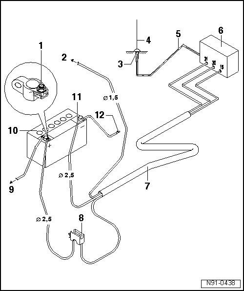
- Positive Connection
- Red wire with suitable connection
- To Terminal 15a
- Connection to terminal 15a.
- Ensure wire is protected by fuse
- Fuse max. 15 amps
- Antenna Ground
- Ensure correct ground connection to body
- Antenna location must be treated with suitable corrosion protection
- Transceiver Antenna
- Component locations: see table.
- Shielded Antenna Wire
- Wire with coaxial connector
- Telephone or Two-Way Radio Transceiver
- Wiring Harness
- Voltage supply, positive side through a red wire with 2.5 mm2 cross section.
- Voltage supply, negative side through a brow wire with 2.5 mm2 cross section.
- If necessary, wire to terminal 15a via black wire 1.5 mm2 cross section
- Fuse Panel
- Install next to battery
- To the Starter
- Battery
- Installation location in engine compartment
- Negative Wire
- Body Ground
Transmitter Power and Antenna Component Locations
Tiguan
Note
Installing bumpers is no longer permitted by law so as to protect pedestrians.
| Designation | Pmax/Watt | Specified Antenna Installation Locations |
| Shortwave less than 54 MHZ | 100 (PEAK). | All locations on the roof |
| 4 m-Band | 20 (eff.). | All locations (on vehicle exterior) |
| 2 m-Band | 20 (eff.) | Front fender / Roof midline front / Roof midline/ Roof midline rear |
| 2 m-Band | 50 (eff.) | Center of roof/ Rear center of roof |
| 70 cm | 50 (eff.) | Front center of roof / Center of roof / Rear center of roof |
| 23 cm | 20 (eff.) | All locations (on vehicle exterior) |
| TETRA/ TETRAPOL | 25 (eff.) | All locations (on vehicle exterior) |
| D-net GSM 900 | 20 (PEAK) | All locations (on vehicle exterior) |
| E-net GSM 1800/ GSM 1900/ UMTS | 10 (PEAK) | All locations (on vehicle exterior) |
1) PEAK = max. carrier power (Peak Envelope Power)
2) eff. = effective transmission output
Note
- Deviations from these guidelines (location of antenna, frequency, output) are only permitted in special isolated cases after a single-case test carried out in the center of VW AG in Wolfsburg.
- EMV = Electromagnetic Compatibility.
Interference Suppression
Interference Suppression Measures
All electrical consumers in the vehicle are individually suppressed.This includes all sensors, actuators, all electrical motors in the vehicle and controllers in control modules that could cause high-frequency interference.
To suppress interference, all electrical parts such as, for example, condensers, coils, and diodes are integrated in the electrical components.Interference suppression components are also built into the connector housings for electrical consumers.
The grounding cables that used to be employed for shielding purposes are no longer used because interference suppression is now done as near as possible to the source of the interference. Compass System
General Information
Note
Before troubleshooting or servicing, the technicians must be familiar
with the function and operation of the compass system. Refer to the Owner's
Manual
Use "Guided Fa ...
 Mobile Online Services
General Information
Mobile Online Services are only available with a Radio/RNS -RX1-.In vehicles
with a telephone, the telephone function is integrated in the Control Module For
Emergency Call Modul ...
See More:
Volkswagen Tiguan Service and Repair Manual > Top Coats: Aquaplus System (Pearl Effect and Heliochrome)
Definition:
Water-Based Pearl Effect Base Paint -LPW 040 ...-
Water-Based Heliochrome Base Paint -LHW 046 ...-
Water-Based Pearl Effect Mixed Paint -LWM 076 ...-
Product Description
The Aquaplus System is a high-quality water-soluble basepaint system based on
special PU dispersions.
The basepa ...
Volkswagen Tiguan Owners Manual
Volkswagen Tiguan Service and Repair Manual
- Body exterior
- Body Interior
- General Paint Information
- Paint
- Brake System
- Suspension, Wheels, Steering
- Wheel and Tire Guide
- Towing Guide
- Wheel and Tire Guide General Information
- Communication
- Electrical Equipment General Information
- Electrical Equipment from 06/2011
- Heating, Ventilation and Air Conditioning
- Refrigerant R134a Servicing
- 6-Speed Manual Transmission 02Q, OBB, and OFB
