Volkswagen Tiguan Service and Repair Manual: Adaptive Chassis DCC, Components
Overview - Adaptive Chassis DCC, Components
Caution
The body acceleration sensors may not be interchanged with each other.
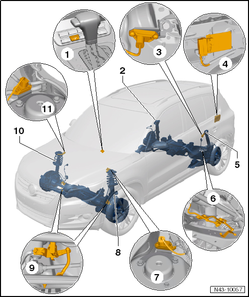
- Damping Adjustment Button -E387-
- Component location: in front of the gearshift lever in the center console
- Explanations.
- Shock Absorber with Right Rear Damping Adjustment Valve -N339-
- Removing and installing, front wheel drive.
- Removing and installing, AWD.
- Rear Body Acceleration Sensor -G343-
- Component location: On the rear left shock absorber mount
- Removing and installing, front wheel drive.
- Removing and installing, AWD.
- Electronic Damping Control Module -J250-
- Component location: Behind the side luggage compartment trim on the left
- Removing and installing.
- If the Electronic Damping Control Module -J250- was replaced, then a basic setting to the adaptive chassis DCC must be performed.
- Shock Absorber with Left Rear Damping Adjustment Valve -N338-
- Removing and installing, front wheel drive.
- Removing and installing, AWD.
- Left Rear Level Control System Sensor -G76-
- Removing and installing, front wheel drive.
- Removing and installing, AWD.
- If the Left Rear Level Control System Sensor -G76- was removed and then installed, then a basic setting to the adaptive chassis must be performed.
Headlamps basic setting. Refer to Vehicle Diagnostic Tester, in "Guided Fault Finding" function.
- Left Front Body Acceleration Sensor -G341-
- Removing and installing.
- Shock Absorber with Left Front Damping Adjustment Valve -N336-
- Removing and installing the suspension strut.
- Suspension strut, servicing.
- Left Front Level Control System Sensor -G78- and Right Front Level
Control Sensor -G289-
- Removing and installing.
- If the Left Front Level Control System Sensor -G78- and the Right Front Level Control Sensor -G289- were removed and installed, then a basic setting to the adaptive chassis DCC must be performed.
- Headlamps basic setting. Refer to Vehicle Diagnostic Tester, in "Guided
Fault Finding" function.
- Shock Absorber with Right Front Damping Adjustment Valve -N337-
- Removing and installing the suspension strut.
- Suspension strut, servicing.
- Right Front Body Acceleration Sensor -G342-
- Removing and installing.
Damping Adjustment Button -E387-
The Damping Adjustment Button -E387- is located on the right side in front of the gearshift lever in the center console.
The system can be adjusted to three different setting using the Damping Adjustment Button -E387-:
- Normal
- Sport
- Comfort
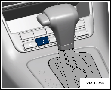
The sequence is -Normal- > -Sport- > -Comfort- > -Normal- > ...
When actively selecting -Sport- and -Comfort- a yellow LED light will light up in the Damping Adjustment Button -E387-.
When -normal- is selected, the Damping Adjustment Button -E387- does not light up.
Left Front Body Acceleration Sensor -G341-, Removing and Installing
Special tools and workshop equipment required
- Torque Wrench -VAG1410-
Removing
- Remove the wiper arms.
- Remove the left plenum chamber cover.
- Disconnect the connector.
- Remove the screws and the Left Front Body Acceleration Sensor -G341-.
Installing
Install in reverse order of removal. Note the following:
Caution
The Front Body Acceleration Sensors must never be interchanged with the Rear Body Acceleration Sensors. Refer to the Parts Catalog for the allocation.
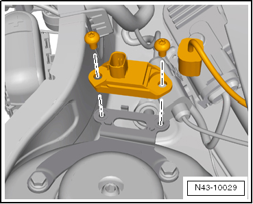
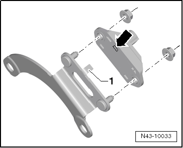
- Be sure to pay attention to the installation position of the Left Front Body Acceleration Sensor -G341- retainer.
The tab on the retainer -1- must fit into the recess in the Left Front Body Acceleration Sensor -G341--arrow-.

Note
Be sure to use the correct retainer. An "LA" is stamped on the retainer
Tightening Specifications
| Component | Tightening Specification |
| Left Front Body Acceleration Sensor -G341- to the retainer | 5 Nm |
Right Front Body Acceleration Sensor -G342-, Removing and Installing
Special tools and workshop equipment required
- Torque Wrench -VAG1410-
Removing
- Remove the wiper arms.
- Remove the left and right plenum chamber cover.
- Disconnect the connector.
- Remove the nuts and remove the Right Front Body Acceleration Sensor -G342-.
Installing
Install in reverse order of removal. Note the following:
Caution
The Front Body Acceleration Sensors must never be interchanged with the Rear Body Acceleration Sensors. Refer to the Parts Catalog for the allocation.
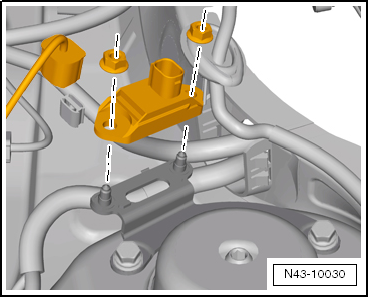
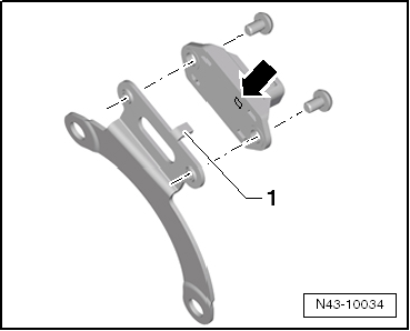
- Be sure to pay attention to the installation position of the Right Front Body Acceleration Sensor -G342- retainer.
The tab on the retainer -1- must fit into the recess in the Right Front Body Acceleration Sensor -G342--arrow-.
Note
Be sure to use the correct retainer. An "R" is stamped on the retainer.
Tightening Specifications
| Component | Tightening Specification |
| Right Front Body Acceleration Sensor -G342- to the retainer | 5 Nm |
Left and Right Front Body Acceleration Sensors -G341/G342-, Replacing
Special tools and workshop equipment required
- Torque Wrench 1331 5-50Nm -VAG1331-
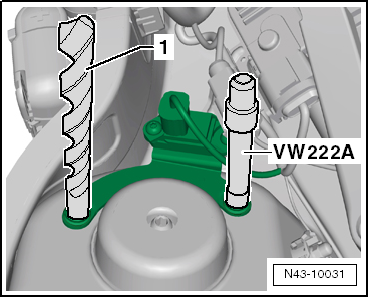
- Pilot Drift -VW222A-
- Spiral bore diameter: 11 mm
Removing
- Remove the Left Front Body Acceleration Sensor -G341-.
- Remove the Right Front Body Acceleration Sensor -G342-.
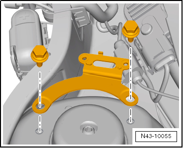
- Remove the retainer bolts and remove the retainer from the shock absorber dome.
Installing
Caution
The body acceleration sensors must not be interchanged. Refer to the Parts Catalog for the allocation.
- Clean the shock absorber dome.
Left Front Body Acceleration Sensor -G341-
- Attach the Front Left Body Acceleration Sensor -G341- to the retainer.
- Be sure to pay attention to the installation position of the Left Front Body Acceleration Sensor -G341- retainer.
The tab on the retainer -1- must fit into the recess in the Left Front Body Acceleration Sensor -G341--arrow-.
Note
Be sure to use the correct retainer. An "LA" is stamped on the retainer
Right Front Body Acceleration Sensor -G342-
- Attach the Right Front Body Acceleration Sensor -G342- to the retainer.
- Be sure to pay attention to the installation position of the Right Front Body Acceleration Sensor -G342- retainer.
The tab on the retainer -1- must fit into the recess in the Right Front Body Acceleration Sensor -G342--arrow-.

Note
Be sure to use the correct retainer. An "R" is stamped on the retainer.
Continuation for Both Sides
- Remove the adhesive on the sealing surfaces of the retainer and apply two-sided adhesive tape.
- Using an 11 mm drill, secure the retainer and the Pilot Drift -VW222A-.
Note
The holes in the retainer must align with the holes in the shock absorber dome.
- Install the screws on after the other by hand and then tighten to the tightening specification.
- Connect the connector to the body acceleration sensor.
Tightening Specifications
| Component | Tightening Specification |
Suspension strut to body
(suspension strut tower)
|
15 Nm + 90º |
Overview - Left/Right Front Level Control System Sensor -G78/G289- for the Adaptive Chassis DDC
Note
- A replacement Left and Right Front Level Control System Sensor -G78/G289- comes complete with the coupling rod and the upper and lower retaining plate.
- Replacing with the subframe installed.
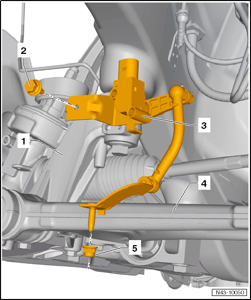
- Subframe
- Bolt
- 9 Nm
- M6 x 16
- Left Front Level Control System Sensor -G78- and Right Front Level
Control Sensor -G289-
- Complete with attachments
- The lever -arrow- must point toward the vehicle exterior
- Removing and installing.
- If the Left Front Level Control System Sensor -G78- and the Right Front Level Control Sensor -G289- were removed and installed, then a basic setting to the adaptive chassis DCC must be performed.
- After replacing, perform basic setting of the headlamps
Headlamps basic setting. Refer to Vehicle Diagnostic Tester, in "Guided Fault Finding" function.
- Control Arm
- Nut
- 9 Nm
- Self-locking
- Always replace if removed
Left and Right Front Level Control System Sensors -G78/G289-, Removing and Installing
Special tools and workshop equipment required
- Torque Wrench 1331 5-50Nm -VAG1331-
Removing
Note
- In order to be able to remove the Left Front Level Control System Sensor -G78- the steering wheel must be turned all the way to the right; this assures that there is enough clearance between the control arm and the stabilizer bar.
- In order to be able to remove the Right Front Level Control Sensor -G289- the steering wheel must be turned all the way to the right; this assures that there is enough clearance between the control arm and the stabilizer bar.
- Disconnect the connector.
- Remove the bolt and the nut.
- Remove the vehicle level sensor.
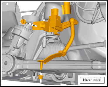
Installing
Install in reverse order of removal. Note the following:
Note
- The level control system sensor lever must point toward vehicle exterior.
- The thread on the vehicle level sensor must be installed into the front hole in the control arm. The tab on the vehicle level sensor retainer must lock into the rear hole in order to assure a correct installation position.
- Perform a basic setting on the adaptive chassis DCC.
- Perform a basic setting on the headlamps Vehicle Diagnostic Tester, in "Guided Fault Finding" function
Tightening Specifications
| Component | Tightening Specification |
| Bolt to subframe | 9 Nm |
Nut
|
9 Nm |
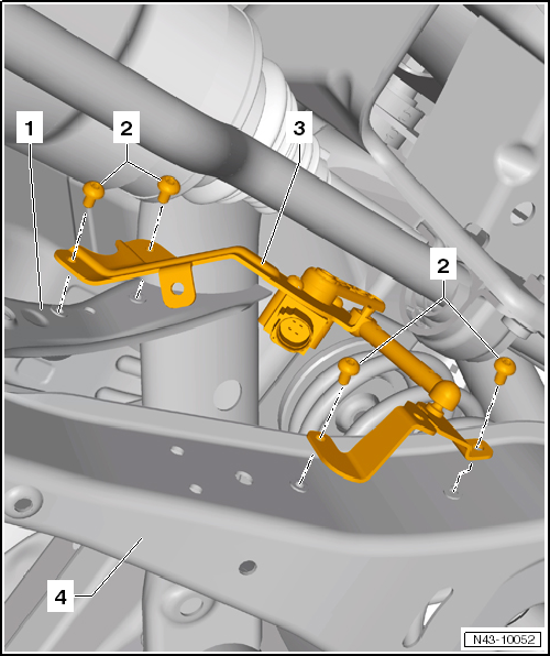
Overview - Left Rear Level Control System Sensor -G76- Adaptive Chassis DCC, FWD
Note
- Vehicle level sensor is available as replacement part only complete with coupling rod and upper and lower retaining plates
- Replacing with subframe installed.
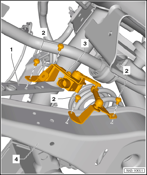
- Subframe
- Bolt
- 5 Nm
- M5 x 20
- Left Rear Level Control System Sensor -G76-
- Complete with attachments
- The lever -arrow- must point toward the vehicle exterior
- Removing and installing.
- If the Left Rear Level Control System Sensor -G76- was removed and then installed, then a basic setting to the adaptive chassis must be performed.
- After replacing, perform basic setting of the headlamps
Headlamps basic setting. Refer to Vehicle Diagnostic Tester, in "Guided Fault Finding" function.
- Lower Transverse Link
Left Rear Level Control System Sensor -G76- for Adaptive Chassis DCC, Removing and Installing, FWD
Special tools and workshop equipment required
- Torque Wrench 1331 5-50Nm -VAG1331-
Removing
- Disconnect the connector.
- Remove the bolts.
- Remove Left Rear Level Control System Sensor -G76-.
Installing
Install in reverse order of removal. Note the following:
The level control system sensor lever must point toward vehicle exterior.
- Perform a basic setting on the adaptive chassis DCC.
- Perform a basic setting on the headlamps Vehicle Diagnostic Tester, in "Guided Fault Finding" function
Tightening Specifications
| Component | Tightening Specification |
| Bolt to subframe/lower transverse link | 5 Nm |
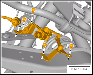
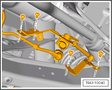
Overview - Left Rear Level Control System Sensor -G76-, Adaptive Chassis DCC, AWD
Note
- Vehicle level sensor is available as replacement part only complete with coupling rod and upper and lower retaining plates.
- Replacing with subframe installed.
- Subframe
- Bolt
- 5 Nm
- M5 x 20
- Left Rear Level Control System Sensor -G76-
- Complete with attachments
- The lever -arrow- must point toward the vehicle exterior
- Removing and installing.
- if the Left Rear Level Control System Sensor -G76- was removed and then installed, then a basic setting to the adaptive chassis must be performed.
- After replacing, perform basic setting of the headlamps
Headlamps basic setting. Refer to Vehicle Diagnostic Tester, in "Guided Fault Finding" function.
- Lower Transverse Link
Left Rear Level Control System Sensor -G76-, Removing and Installing, Adaptive Chassis DCC, AWD
Special tools and workshop equipment required
- Torque Wrench 1331 5-50Nm -VAG1331-
Removing
- Disconnect the connector.
- Remove the bolts.
- Remove Left Rear Level Control System Sensor -G76-.
Installing
Install in reverse order of removal. Note the following:
The level control system sensor lever must point toward vehicle exterior.
- Perform a basic setting on the adaptive chassis DCC.
- Perform a basic setting on the headlamps Vehicle Diagnostic Tester, in "Guided Fault Finding" function
Tightening Specifications
| Component | Tightening Specification |
| Bolt to subframe/lower transverse link | 5 Nm |
Electronic Damping Control Module -J250-, Removing and Installing
Removing
Component location: behind the side luggage compartment trim on the left
- Turn off all electrical consumers.
- Remove the ignition key.
- Remove the left side trim in the luggage compartment.
- Disconnect the connector
- Remove the Electronic Damping Control Module -J250- from the side panel above the wheel housing.
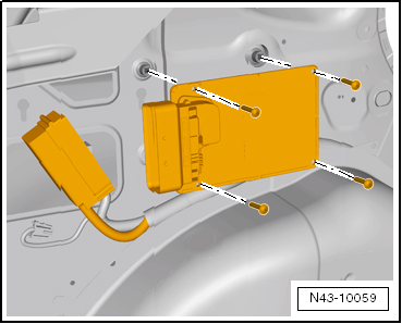
Installing
Install in reverse order of removal while noting the following:
- Perform a basic setting on the adaptive chassis DCC.
Adaptive Chassis DCC, Basic Setting
- Connect the Vehicle Diagnostic Tester and select "Guided Fault Finding".
Wheel damping electronics
FunctionsBasic setting
Follow the instructions on the screen to perform the basic setting.Left Front Axle Wire Routing
Note
- Always check the wire routing.
- Always make sure that all the wires are attached in order and are not twisted in their retainer.
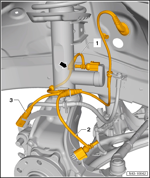
- Left Front Dampening Adjustment Valve -N336- Wire
- The wire must be mounted in the retainer on the shock absorber -arrow-
- Left Front ABS Wheel Speed Sensor -G47- Wire
- Brake Pad Wear Indicator Wire
Right Front Axle Wire Routing
Note
- Always check the wire routing.
- Always make sure that all the wires are attached in order and are not twisted in their retainer.
- Right Front Dampening Adjustment Valve -N337- Wire
- The wire must be mounted in the retainer on the shock absorber -arrow-
- Right Front ABS Wheel Speed Sensor -G45- Wire
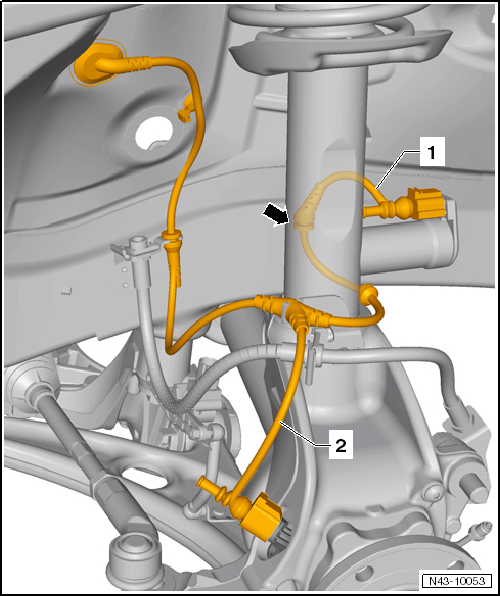
Rear Axle Wire Routing
Note
- Always check the wire routing.
- Always make sure that all the wires are attached in order and are not twisted in their retainer.
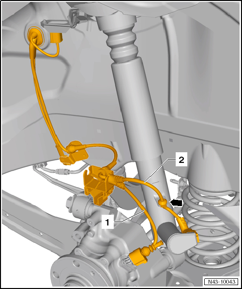
- Left and Right Rear Dampening Adjustment Valve -N338/N339- Wire
- The wire must be mounted in the retainer on the shock absorber -arrow-
- Right and Left Rear ABS Wheel Speed Sensor -G44/G46- Wire

 Adaptive Chassis DCC Suspension Strut
Overview - Adaptive Chassis DCC Suspension Strut
Shock Absorber with Left Front Damping Adjustment Valve -N336-
Can be replaced individually
Allocation. Refer to the Parts Catalog.
Stop B ...
See More:
Volkswagen Tiguan Service and Repair Manual > Communication: Antenna Systems, RCD 300, 500 RNS 300 and Premium 7
General Information
Antenna System.
Vehicles without radio have no rear window antenna and a
"dummy" antenna without any connections is
installed on the roof.
"RCD 300", "RCD 310" and "RCD 500" radios have a rear window antenna
with a right antenna amplifier as well as a roof antenna with a ...
Volkswagen Tiguan Owners Manual
Volkswagen Tiguan Service and Repair Manual
- Body exterior
- Body Interior
- General Paint Information
- Paint
- Brake System
- Suspension, Wheels, Steering
- Wheel and Tire Guide
- Towing Guide
- Wheel and Tire Guide General Information
- Communication
- Electrical Equipment General Information
- Electrical Equipment from 06/2011
- Heating, Ventilation and Air Conditioning
- Refrigerant R134a Servicing
- 6-Speed Manual Transmission 02Q, OBB, and OFB
