Volkswagen Tiguan Service and Repair Manual: Transverse Link, Tie Rod, AWD
Overview - Transverse Link, Tie Rod, AWD
The -arrow- points in the direction of travel.
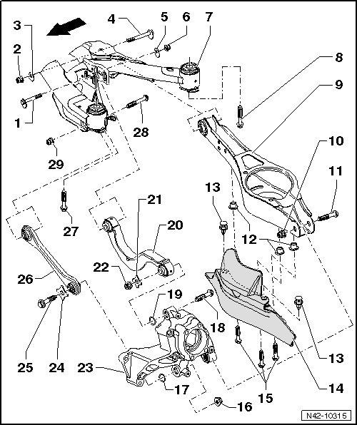
- Eccentric Bolt
- Perform a vehicle alignment after loosening.
- Do not turn more than 90º right or left (that is smallest to largest possible adjustment)
- Nut
- 95 Nm
- Always replace if removed
- M12 x 1.5
- Self-locking
- When adjusting, can be loosened and tightened up to 5 times
- Always tighten the threaded connections in curb weight position.
- Eccentric Washer
- Inner bore with tab
- Eccentric Bolt
- Perform a vehicle alignment after loosening.
- Do not turn more than 90º right or left (that is smallest to largest possible adjustment)
- Eccentric Washer
- Inner bore with tab
- Nut
- 95 Nm
- Always replace if removed
- M12 x 1.5
- Self-locking
- When adjusting, can be loosened and tightened up to 5 times
- Always tighten the threaded connections in curb weight position.
Note
- Adjust the Torque Wrench 40-200Nm -VAG1332- to 80 Nm when tightening the nut.
- This tightening specification does only apply in conjunction with Insert Tool 18mm -T10179-.
- Subframe
- Bolt
- 90 Nm +90º
- Always replace if removed
- M12 x 1.5 x 125
- Lower Transverse Link
- Removing and installing.
- Nut
- 90 Nm +90º
- Always replace if removed
- Self-locking
- Always tighten the threaded connections in curb weight position.
- Bolt
- Always replace if removed
- M12 x 1.5 x 75
- Threaded Rivet
- M6
- Expanding Rivet
- Stone Chip Protection
- Hex Bolt
- 8 Nm
- M6 x 12
- Nut
- Always replace if removed
- Self-locking
- Always tighten the threaded connections in curb weight position.
- Washer
- Bolt
- 150 Nm + 90º
- M14 x 1.5 x 115
- Always replace if removed
- Always tighten the threaded connections in curb weight position.
- Washer
- Upper Transverse Link
- Removing and installing.
- Washer
- Nut
- Self-locking
- Always replace if removed
- Wheel Bearing Housing
- Removing and installing.
- Washer
- Bolt
- 150 Nm + 90º
- Always replace if removed
- M14 x 1.5 x 115
- Always tighten the threaded connections in curb weight position.
- Tie rod
- There are different versions.
- Closed in direction of travel (the right and left tie rods are different)
- Opened downward (the right and left tie rods are the same)
- It is possible to interchange
- Pay attention to the allocation of the trailing arms when replacing them.
- Removing and installing.
- Bolt
- 90 Nm +90º
- Always replace if removed
- M12 x 1.5 x 125
- Bolt
- Always replace if removed
- M12 x 1.5 x 95
- Always tighten the threaded connections in curb weight position.
- Nut
- 90 Nm +90º
- Self-locking
- Always replace if removed
Overview - Left Rear Level Control System Sensor -G76-
Note
- Overview - Left Rear Level Control System Sensor -G76-, Adaptive Chassis DCC, AWD.
- Vehicle level sensor is available as replacement part only complete with coupling rod and upper and lower retaining plates.
- Replacing with subframe installed.
- Headlamp Range Control Module -J431-
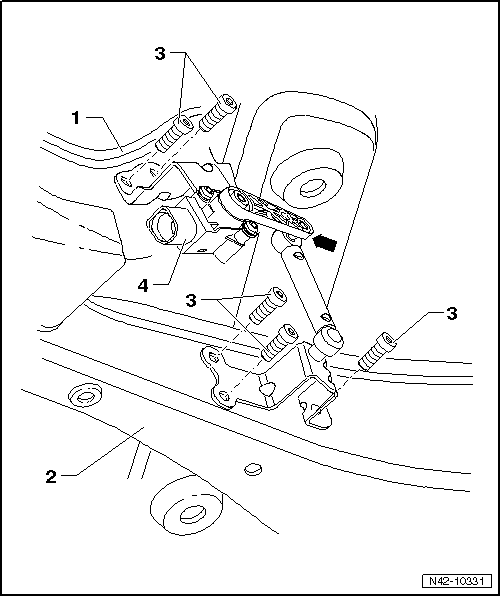
- Subframe
- Lower Transverse Link
- Bolt
- 5 Nm
- M5 x 20
- Left Rear Level Control System Sensor -G76-
- Complete with attachments
- Lever -arrow- must point toward vehicle exterior
- Replace in vehicle.
- After replacing, perform basic setting of the headlamps
Headlamps basic setting. Refer to Vehicle Diagnostic Tester, in "Guided Fault Finding" function.
Left Rear Level Control System Sensor -G76-, Removing and Installing
Special tools and workshop equipment required
- Torque Wrench 1331 5-50Nm -VAG1331-
Note
Left Rear Level Control System Sensor -G76-, Removing and Installing, Adaptive Chassis DCC, AWD.
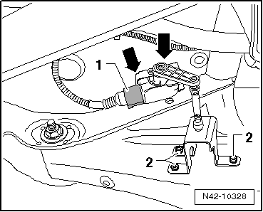
Removing
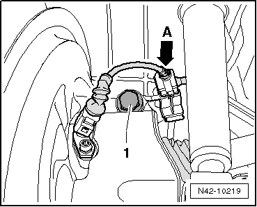
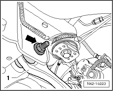
- Disconnect the connector -1-.
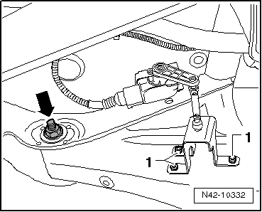
- Remove the bolts -2- from the lower transverse link.
- Remove bolts -arrows- from the subframe.
- Remove Left Rear Level Control System Sensor -G76-.
Installing
Install in reverse order of removal. Note the following:
The Left Rear Level Control System Sensor -G76- lever must point toward the outside of the vehicle.
- After replacing, perform a headlamp basic setting Vehicle Diagnostic Tester, in "Guided Fault Finding" function
Tightening Specifications
| Component | Tightening Specification |
| Left Rear Level Control System Sensor -G76- to lower transverse link and subframe | 5 Nm |
Upper Transverse Link, Removing and Installing
Special tools and workshop equipment required
- Torque Wrench 1332 40-200Nm -VAG1332-
Removing
- Remove the wheel.
- Remove coil spring.
- Unhook speed sensor wiring -arrow A- from the upper transverse link.
- Remove the bolt -1-.

- Mark, for example using a felt-tip marker, position of eccentric bolt -arrow- to subframe.
- Remove the bolt -arrow-.
- Remove upper transverse link -1-.
Installing
- Insert the upper transverse link into the vehicle and tighten the bolts by hand.
Only bolt on transverse link if dimension "a" is reached.
- Fasten upper transverse link -1- to the subframe and tighten the new nut -arrow-.
- Note applied marking of eccentric bolt -arrow- to subframe.

- Tighten the bolt -1- on the upper transverse link.
Note
Make sure that washer is installed between bolt and wheel bearing housing.
- Hook speed sensor wiring -arrow A- in at the upper transverse link.
- Install coil spring.
- Install the wheel and tighten.
- Perform vehicle alignment.
Tightening Specifications
| Component | Tightening Specification |
Upper transverse link to
wheel bearing housing
|
150 Nm + 90º |
Upper transverse link to
subframe
|
95 Nm
|
Lower Transverse Link, Removing and Installing
Special tools and workshop equipment required
- Torque Wrench 1332 40-200Nm -VAG1332-
Removing
- Remove the wheel.
- Remove coil spring.
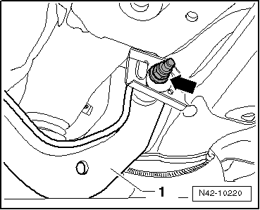
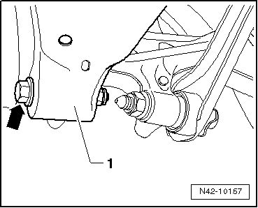
- Remove bolt -arrow- for lower transverse link -1-.

Vehicles with Automatic Headlamp Range Control
- Remove the bolts -1- from the lower transverse link.
Continuation for All Vehicles
- Mark, for example using a felt-tip marker, position of eccentric bolt -arrow- to subframe.
- Disengage rear exhaust system and lower.
- Remove the bolt -arrow-.
- Remove lower transverse link.

Installing
- Insert lower transverse link into vehicle and tighten the bolts by hand.
Only bolt on transverse link if dimension "a" is reached.
- Connect the upper transverse link to the subframe and tighten the new nut -arrow- to the tightening specification only.
- Note applied marking of eccentric bolt -arrow- to subframe.
- Suspend rear exhaust system.
Vehicles with Automatic Headlamp Range Control
- Install the bolts -1- to the lower transverse link.
Continuation for All Vehicles
- Tighten bolt -arrow- for lower transverse link -1-.
- Install coil spring.
- Install the wheel and tighten.
- Perform vehicle alignment.
Tightening Specifications
| Component | Tightening Specification |
Lower transverse link to
wheel bearing housing
|
90 Nm +90º |
Lower transverse link to
subframe
|
95 Nm |
| Left Rear Level Control System Sensor -G76- to lower transverse link | 5 Nm |
Tie Rod, Removing and Installing
Special tools and workshop equipment required
- Torque Wrench 1331 5-50Nm -VAG1331-
- Torque Wrench 1332 40-200Nm -VAG1332-
Removing
- Remove the wheel.
- Remove coil spring.
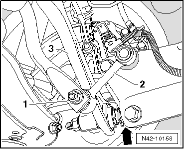
- Remove the nut -1- and pull the coupling rod -2- out of the stabilizer bar.
- Remove bolt -arrow- for tie rod -3-.

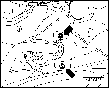
- Remove the bolts -arrows- for the stabilizer bar clamp.

If the upper bolts on the stabilizer bar clamp on the right side of the vehicle cannot be removed, then the following work steps must be performed.
Only for the Right Vehicle Side (depending on equipment)
- Now secure vehicle on both sides to lifting arms on hoist with Tensioning Strap -T10038-.
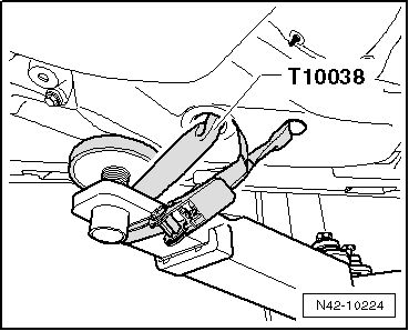
WARNING
If vehicle is not secured, it could slide off of hoist.
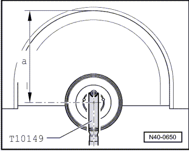
- Install Engine/Gearbox Jack Adapter - Wheel Hub Support -T10149- with wheel bolt on wheel hub.
- Lift the wheel hub with the Engine/Gearbox Jack Adapter - Wheel Hub Support -T10149- and Engine/Gearbox Jack -VAG1383A- far enough until it is possible to access the bolts on the right stabilizer bar clamp.
Procedure for Both Vehicles Sides
- Remove the nut -arrow- and remove bolt toward rear.
- Remove tie rod -1-.

Installing
Caution
Pay attention to the different trailing arm versions when replacing the tie rod.
Note the allocation of the tie rods for the trailing arms.
- Insert tie rod into vehicle and tighten the bolts by hand.
Note
Pay attention to the different versions of the tie rods: open underneath or closed in direction of travel.
The bolted connections of the tie rod must only be fastened when the dimension "a" is achieved.
- Fasten the tie rod -1- to the subframe and tighten the new nut -arrow-.
- Tighten bolts -arrows- for stabilizer clamp.
Only for the Right Vehicle Side (depending on equipment)
- Lower the suspension again using Engine and Gearbox Jack -VAS6931- and remove Engine/Gearbox Jack Adapter - Wheel Hub Support -T10149- from wheel hub.
- Remove the Tensioning Strap -T10038-.
Procedure for Both Vehicles Sides
- Tighten bolt -arrow- for tie rod -3-.
Note
Make sure that washer is installed between nut and wheel bearing housing.
- Insert coupling rod -2- into stabilizer and tighten nut -1-.
- Install coil spring.
- Install the wheel and tighten.
- Perform vehicle alignment.
Tightening Specifications
| Component | Tightening Specification |
Tie rod to steering
knuckle
|
150 Nm + 90º |
Tie rod to subframe
|
90 Nm +90º |
Stabilizer bar to
subframe
|
25 Nm + 45º |
Stabilizer bar to coupling rod
|
40 Nm |
 Subframe, Servicing, from 05/28/2012
Front Bonded Rubber Bushing, Replacing
Special tools and workshop equipment required
Tensioning Strap -T10038-
Hydraulic Press - Rear Subframe Bushing Tool Kit -T10263-
Subframe Bushing Assembly T ...
 Wheel Bearing Housing, Trailing Arm, AWD
Overview - Wheel Bearing Housing, Trailing Arm, AWD
The -arrow- points in the direction of travel.
Cover
Mounting Bracket
Coupling Rod
Connects stabilizer to trailing link/wheel bearing housin ...
See More:
Volkswagen Tiguan Service and Repair Manual > Seat Frames: Rear Seats
Tools
Special tools and workshop equipment required
Torque Wrench 1783 - 2-10Nm - VAG1783-
Torque Wrench 1331 5-50Nm - VAG1331-
Torque Wrench 1332 40-200Nm - VAG1332-
Bench Seat, Removing and Installing
Removing
Vehicles with Variable Luggage Compartment Floor
Pull the luggage compartm ...
Volkswagen Tiguan Owners Manual
Volkswagen Tiguan Service and Repair Manual
- Body exterior
- Body Interior
- General Paint Information
- Paint
- Brake System
- Suspension, Wheels, Steering
- Wheel and Tire Guide
- Towing Guide
- Wheel and Tire Guide General Information
- Communication
- Electrical Equipment General Information
- Electrical Equipment from 06/2011
- Heating, Ventilation and Air Conditioning
- Refrigerant R134a Servicing
- 6-Speed Manual Transmission 02Q, OBB, and OFB
